Integrated circuit substrate

An integrated circuit base and substrate technology, which is applied in the direction of circuits, electrical components, and electric solid devices, can solve the problems of inconvenient use, complex circuits, and poor power supply efficiency for customers, and is beneficial to power output and efficiency, inductance and The effect of high coupling coefficient and overcoming inconsistency

Active Publication Date: 2017-03-22
SG MICRO
View PDF4 Cites 2 Cited by
  • Summary
  • Abstract
  • Description
  • Claims
  • Application Information

AI Technical Summary

Problems solved by technology

Because the inductance is not large enough, the signal transmission has to use 180MHz modulation signal, the circuit is very complicated, and the magnetic circuit in the circuit is not closed, the magnetic flux leakage is large, and the EMI electromagnetic interference space radiation is large
The inventors found that for the semiconductor isolation technology using the micro-transformer scheme, due to the inductance of the micro-transformer scheme, the coupling coefficient is too low, and the complexity of the transmission circuit is also increased, and the efficiency of the integrated power supply is poor.
For some capacitive isolators, users need to add an external transformer
In addition, capacitive isolation cannot integrate the power supply of the switch internally, which is inconvenient for customers to use

Method used


Image

  • Integrated circuit substrate
  • Integrated circuit substrate

Examples


Embodiment Construction

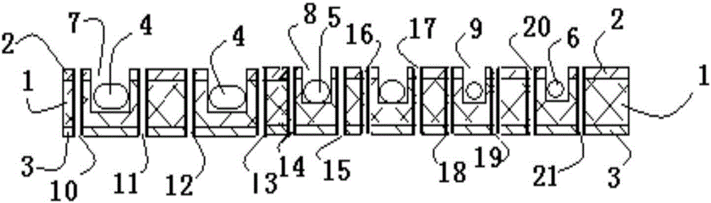
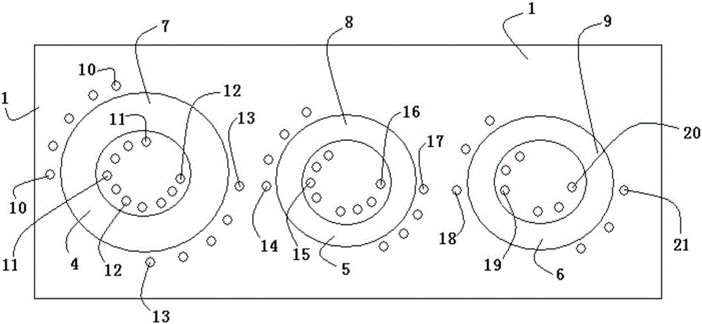
[0021] Below with the accompanying drawings ( Figure 1-Figure 2 ) to illustrate the present invention.

[0022] figure 1 It is a structural schematic diagram of an integrated circuit substrate implementing the present invention, figure 1 The performance is the cross-sectional structure. figure 2 yes figure 1 Schematic diagram of the top view direction. Such as Figure 1 to Figure 2 As shown, an integrated circuit substrate includes a substrate body, the substrate body includes a copper clad core board, and the copper clad core board includes a core board 1 and an upper copper clad layer 2 bonded to the surface of the core board 1 and bonded to the The lower copper clad layer 3 on the bottom surface of the core board 1, the core board 1 is provided with an upwardly facing annular groove (such as a first annular groove 7; a second annular groove 8; a third annular groove 9), and the opening extends to the outside of the upper copper clad layer 2 . The annular groove is ...


PUM


Abstract

The invention relates to an integrated circuit substrate. The substrate comprises a copper coated core board, wherein the circuit function of the integrated circuit package substrate is favorably improved or extended by forming an annular groove for accommodating a magnetic ring in the copper coated core board, i.e., a micro transformer can be integrated in the integrated circuit substrate by winding connection on via holes which are internally and externally distributed along the magnetic ring, the copper coated core board is characterized by comprising a substrate body, the substrate body comprises the copper coated core board, the copper coated core board comprises a core board, an upper copper coated layer and a lower copper coated layer, the upper copper coated layer is combined with a surface of the core board, the lower copper coated layer is combined with a bottom surface of the core board, the annular groove is formed in the core board and is provided with an opening facing upwards, and the opening extends out of the upper copper coated layer.

Description

technical field [0001] The invention relates to integrated circuit packaging technology, in particular to an integrated circuit substrate. The substrate includes a copper-clad core board. By setting an annular groove for accommodating a magnetic ring in the copper-clad core board, it is beneficial to improve or expand the performance of the integrated circuit packaging substrate. For circuit functions, for example, the microtransformer can be integrated in the integrated circuit substrate by winding and connecting the via holes distributed along the inside and outside of the magnetic ring. Background technique [0002] Due to the vigorous development of new energy, more and more isolation applications are required and the isolation voltage is getting higher and higher, while semiconductor isolation technology replaces traditional optocoupler technology with higher efficiency, higher integration, and higher transmission rates, which is in line with the development of the indus...

Claims


Application Information

Patent Timeline
Patent Type & Authority Applications(China)
IPC IPC(8): H01L23/498
CPCH01L23/49805H01L23/49838
Inventor 李志林谭磊
Owner SG MICRO
Why Eureka
Try Eureka