
Method, processing machine and computer program product for image-based positioning of workpiece processing

A processing process and machine technology, applied in computer control, program control, metal processing, etc., can solve problems such as error-prone, time-consuming, inaccurate, etc., to save time and avoid errors.

Active Publication Date: 2018-09-14
TRUMPF WERKZEUGMASCHINEN GMBH & CO KG
View PDF6 Cites 0 Cited by
  • Summary
  • Abstract
  • Description
  • Claims
  • Application Information

AI Technical Summary

Problems solved by technology

[0002] The manual positioning or subsequent positioning (repositioning) of the workpiece machining process to be carried out is in many cases time-consuming, imprecise and error-prone

Method used


Image

  • Method, processing machine and computer program product for image-based positioning of workpiece processing
  • Method, processing machine and computer program product for image-based positioning of workpiece processing
  • Method, processing machine and computer program product for image-based positioning of workpiece processing

Examples


Embodiment Construction

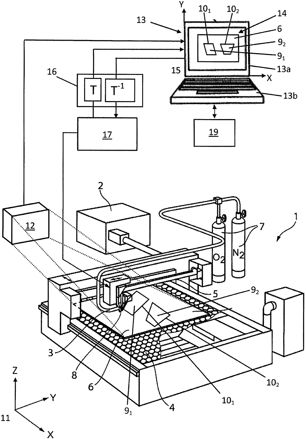
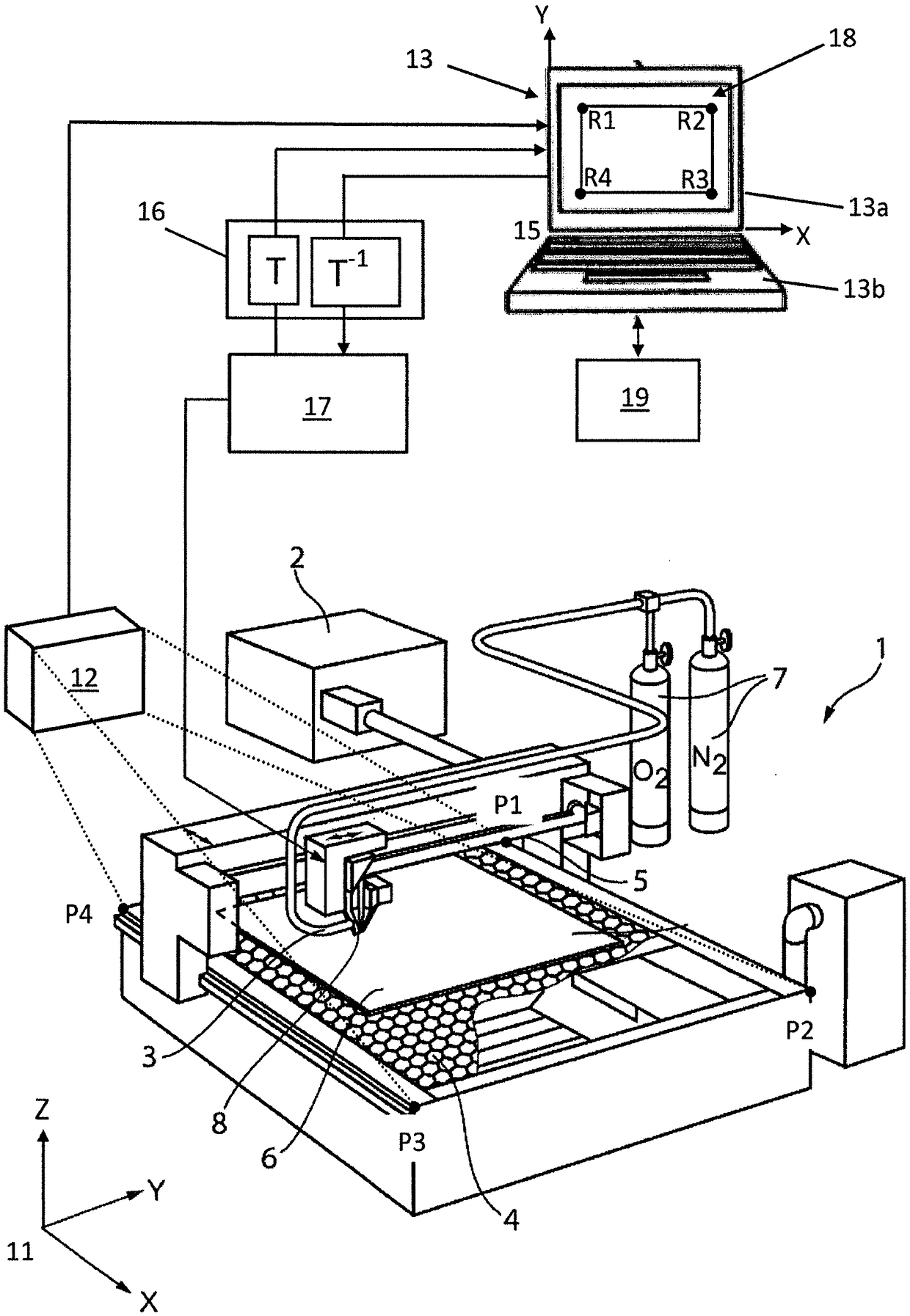
[0037] figure 1 The laser cutting machine 1 shown three-dimensionally as a platform machine includes, for example, a CO 2 A laser beam generator 2 of a laser, a diode laser or a solid-state laser, the laser cutting machine also includes a laser processing head 3 and a workpiece support 4 that can move in the X and Y directions. A laser beam 5 is generated in the laser beam generator 2 , which is guided from the laser beam generator 2 to the laser processing head 3 by means of an optical cable (not shown) or a deflection mirror (not shown). The laser beam 5 is directed by means of a focusing lens arranged in the laser processing head 3 onto a workpiece 6 (for example a sheet metal) located on the workpiece support 4 . Furthermore, the laser cutting machine 1 is supplied with process gases 7 , such as oxygen and nitrogen. A process gas 7 is fed to a process gas nozzle 8 of the laser machining head 3 , from which process gas emerges together with the laser beam 5 . Laser cutti...


PUM


Abstract

The method according to the invention for processing a flat workpiece (6), in particular a sheet metal or a three-dimensional workpiece (6') on a processing machine (1), in particular a machine tool or a laser cutting machine, has the following steps: a) Sensing a live image (14) of a workpiece (6; 6') to be processed by means of an image sensing device (12) for sensing a two-dimensional image; b) at all locations on said workpiece (6; 6') The predetermined forward transformation (T, T') from the three-dimensional machine coordinate system (11) to the two-dimensional live image coordinate system (15) in the live image (14) through the workpiece machining process (101, 102, 103) ) display of at least one workpiece machining process (101, 102, 103) to be carried out; c) manual repositioning of the workpiece machining process to be carried out in the live image (14) of the workpiece (6; 6') (101, 102, 103); and d) predetermination of the workpiece machining process (101, 102, 103) from the two-dimensional live image coordinate system (15) to the three-dimensional machine coordinate system (11) by repositioning The reverse transformation (T-1, T'-1) is used to implement the workpiece machining process (101, 102, 103) on the workpiece (6; 6').

Description

technical field [0001] The invention relates to a method for processing flat workpieces, in particular sheet metal or three-dimensional workpieces, on a processing machine, in particular a power tool or a laser cutting machine, as well as a suitable processing machine and a suitable processing machine for carrying out the method. A corresponding computer program product. Background technique [0002] The manual or subsequent positioning (repositioning) of the workpiece machining process to be carried out is in many cases time-consuming, imprecise and error-prone. First, the component dimensions must be determined, then the raw material must be measured manually, and finally the starting point must be determined, for example by means of a laser diode. Since this information is often insufficient, a dry run is often first carried out in order to avoid incorrect production or damage to the processing machine. [0003] It is known from JP 11-320143 to scan the sheet metal to b...

Claims


Application Information

Patent Timeline
Patent Type & Authority Patents(China)
IPC IPC(8): G05B19/401B23K37/02B23K37/04B23K26/03B23K26/08B23K26/14B23K26/38G05B19/408G05B19/4097B23K101/18
CPCB23K26/032B23K26/0876B23K26/14B23K26/1464B23K26/38B23K37/0235B23K37/0408G05B19/401G05B19/4086G05B19/4097G05B2219/37009G05B2219/35162G05B2219/35075G05B2219/35506G05B2219/45041G05B2219/45234B23K2101/18
Inventor J·奥特纳德M·基弗
Owner TRUMPF WERKZEUGMASCHINEN GMBH & CO KG
Learn More