Method for replacing test section of continuous transonic wind tunnel

A replacement method and transonic technology, applied in aerodynamic tests, machine/structural component testing, measuring devices, etc., can solve problems such as gas waste in continuous transonic wind tunnels

Inactive Publication Date: 2017-03-29
CHINA AVIATION PLANNING & DESIGN INST GRP +1
View PDF4 Cites 14 Cited by
  • Summary
  • Abstract
  • Description
  • Claims
  • Application Information

AI Technical Summary

Problems solved by technology

[0003] The present invention is aimed at the deficiencies in the above-mentioned existing devices and provides a method for replacing the test section of a continuous transonic wind tunnel, which aims to solve the problem of gas waste in a continuous transonic wind tunnel

Method used


Image

  • Method for replacing test section of continuous transonic wind tunnel
  • Method for replacing test section of continuous transonic wind tunnel
  • Method for replacing test section of continuous transonic wind tunnel

Examples


Embodiment Construction

[0011] The technical scheme of the present invention will be described in further detail below in conjunction with accompanying drawing and embodiment:

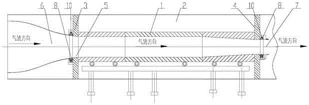
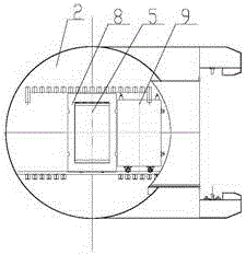
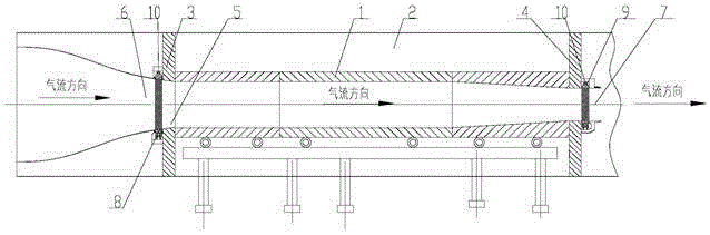
[0012] See attached Figure 1~4 As shown in the test section replacement method of this kind of continuous transonic wind tunnel, the test section 1 of the continuous transonic wind tunnel is located in the inner center of the chamber 2 of the continuous transonic wind tunnel, and the two ends of the chamber 2 are respectively arranged There are a front load-bearing wall 3 and a rear load-bearing wall 4, and there are respectively test flow channels 5 on the front load-bearing wall 3 and the rear load-bearing wall 4. The outflow side 7 of the force wall 4 is respectively provided with a diversion door 8 for flow diversion and an isolation door 9 for flow interception. The diversion door 8 and the isolation door 9 are installed on a guide rail 10. When the continuous transonic wind When the hole is in the working state, the f...


PUM


Abstract

The invention relates to a method for replacing the test section of a continuous transonic wind tunnel. According to the method, a diversion door (8) and an isolation door (9) are arranged on the side of a force bearing wall. When there is a need to replace a test section (1), the isolation door (9) is in the middle position of the force bearing wall, a plenum chamber (2) is isolated from the remaining loop of a continuous transonic wind tunnel, and the test section (1) can be replaced by only replacing the gas inside the plenum chamber (2). During test, the diversion door (8) is kept in the middle position of the force bearing wall. Thus, the backflow in the whole closed loop is smooth, and smooth test is ensured.

Description

technical field [0001] The invention relates to a method for replacing a test section of a continuous transonic wind tunnel, which belongs to the cavity structure of the continuous transonic wind tunnel. Background technique [0002] The continuous transonic wind tunnel is a closed loop, the entire container reaches 15,000 cubic meters, and the test section is located inside the chamber. The resident chamber is a cylindrical shell with a circular cross section, and a rectangular hole is opened on the side of the resident chamber. The test section enters and exits the room through this hole, and this hole needs to be sealed with the door of the room. According to different test requirements, the test section needs to be replaced. When the test section is replaced, the pressured gas in the circuit needs to be emptied. After the test section is replaced, the entire wind tunnel circuit needs to be pressed again until the test needs pressure. This process needs to consume a la...

Claims


Application Information

Patent Timeline
Patent Type & Authority Applications(China)
IPC IPC(8): G01M9/02
CPCG01M9/02
Inventor 郄方端木兵雷赵燕平
Owner CHINA AVIATION PLANNING & DESIGN INST GRP
Why Eureka
Try Eureka