
Anti-falling device for power test climbing

An electric power test and anti-drop technology, which is applied in the direction of overhead line/cable equipment, safety belts, life-saving equipment, etc., can solve problems such as decoupling, breakage, casualties, etc., achieve good tensile performance, firm connection, and avoid personal injury Effect

Inactive Publication Date: 2017-03-29
PENGLAI POWER SUPPLY CO OF STATE GRID SHANDONG ELECTRIC POWER CO
View PDF3 Cites 7 Cited by
  • Summary
  • Abstract
  • Description
  • Claims
  • Application Information

AI Technical Summary

Problems solved by technology

Because when the staff falls, the anti-fall device will be subjected to instantaneous force. The existing anti-fall device is directly hung on the power pole or cable. When the staff suddenly falls, it is prone to decoupling or due to the instantaneous force break, causing casualties

Method used


Image

  • Anti-falling device for power test climbing
  • Anti-falling device for power test climbing

Examples


Embodiment 1

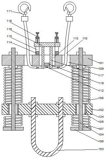
[0024]In the present invention, in order to prevent the overall structure from being deflected due to the shaking of the suspension belt, in this embodiment, preferably, a square hole 113 is provided in the middle of the upper support plate 101, the square hole is a through hole, and the square hole is located at the connecting hole. Between the two through slots, two baffles 114 are arranged above the square hole 113, so that the two baffles are parallel to each other, and the two baffles are respectively perpendicular to the plane where the upper support plate is located. Adjustment holes 115 are respectively arranged on the plate 114, so that the adjustment holes are elongated holes. The length direction of the adjustment holes is perpendicular to the plane where the upper support plate is located. A pressing plate 116 is arranged between the two baffle plates 114, and the pressing plates are parallel to each other. On the plane where the upper support plate is located, the ...

Embodiment 2

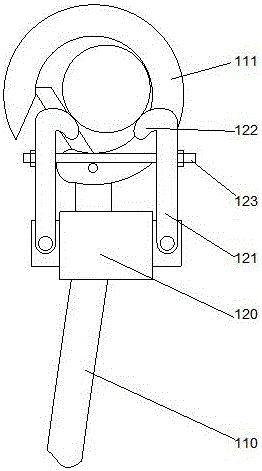
[0027] Such as figure 2 As shown, in this embodiment, on the basis of Embodiment 1, in order to improve the stability of the overall structure and prevent the hook from moving along the length direction of the cable, preferably, the ends of the two suspension straps 110 on the same side are connected to each other , so that the two ends of the two suspension straps are respectively hung on the cable through a hook. In order to facilitate the installation of the hook, a mounting plate 120 is provided on the hook 111, and 2 strip-shaped communication channels can be set on the mounting plate. hole, so that the end of the suspension belt 110 is connected to the installation plate 120, the ends of the suspension belt are respectively hung on the installation plate through two through holes, and the two suspensions are suspended by sewing or other linking methods. The ends of the belt on the same side are all fixed on the mounting plate, positioning rods 121 are respectively arran...


PUM


Abstract

The invention discloses an anti-falling device for power test climbing. The device comprises an upper support plate and a lower support plate, wherein a hanging ring is arranged on the lower end of the lower support plate; at least two connecting rods are arranged on the lower support plate; the upper end of each connecting rod penetrates the upper support plate and is fixed through a nut; a cambered strip-shaped hole is formed on the lower support plate; the lower end of each connecting rod penetrates the strip-shaped hole; a spacing plate is arranged at the end part of the lower end of each connecting rod; a high-strength spring is sleeved on each connecting rod; the lower end of the high-strength spring is propped against the upper end surface of the spacing plate; the upper end of the high-strength spring is propped against the lower end surface of the lower support plate; and a buffer spring is arranged on each connecting rod between the upper plate and the lower plate. Through the adoption of the device disclosed by the invention, the whole structure can be hung on an aerial cable; the structure is stable, safer and more reliable.

Description

technical field [0001] The invention relates to an anti-drop device for electric power test climbing. Background technique [0002] During the maintenance of high-altitude power equipment, in order to improve safety, a fall arrester is usually used and connected to the staff to prevent the maintenance personnel from falling. Because when the staff falls, the anti-fall device will be subjected to instantaneous force. The existing anti-fall device is directly hung on the power pole or cable. When the staff suddenly falls, it is prone to decoupling or due to the instantaneous force break, causing casualties. Contents of the invention [0003] The purpose of the present invention is to provide an anti-falling device for electric power test climbing, which can improve the problems existing in the prior art, so that the overall structure can be suspended on high-altitude cables, the structure is stable, and it is safer and more reliable. [0004] The present invention is reali...

Claims


Application Information

Patent Timeline
Patent Type & Authority Applications(China)
IPC IPC(8): H02G1/02A62B35/00
CPCA62B35/0025H02G1/02
Inventor 吕洪军刘崇业张夕军张学海张瑞宏于学新蒋春旭王楠
Owner PENGLAI POWER SUPPLY CO OF STATE GRID SHANDONG ELECTRIC POWER CO
Learn More