Device and method for delay compensation of passive optical network and passive optical network

A technology of passive optical network and delay compensation, which is applied in multiplexing system selection devices, selection devices, wavelength division multiplexing systems, etc., can solve the problem of difficult to meet the requirements of front-end backhaul for PON transmission delay, pipeline Layout restrictions and other issues

Active Publication Date: 2019-11-29
HUAWEI TECH CO LTD
View PDF3 Cites 0 Cited by
  • Summary
  • Abstract
  • Description
  • Claims
  • Application Information

AI Technical Summary

Problems solved by technology

However, in the actual network deployment process, the main trunk fiber and the backup trunk fiber pass through different pipes, and the layout of the pipes is limited by the city's roads and planning, often resulting in a length difference of more than 6 meters between the main path and the backup path. It is difficult to meet the transmission delay requirements of front-end backhaul for PON

Method used


Image

  • Device and method for delay compensation of passive optical network and passive optical network
  • Device and method for delay compensation of passive optical network and passive optical network
  • Device and method for delay compensation of passive optical network and passive optical network

Examples


Embodiment Construction

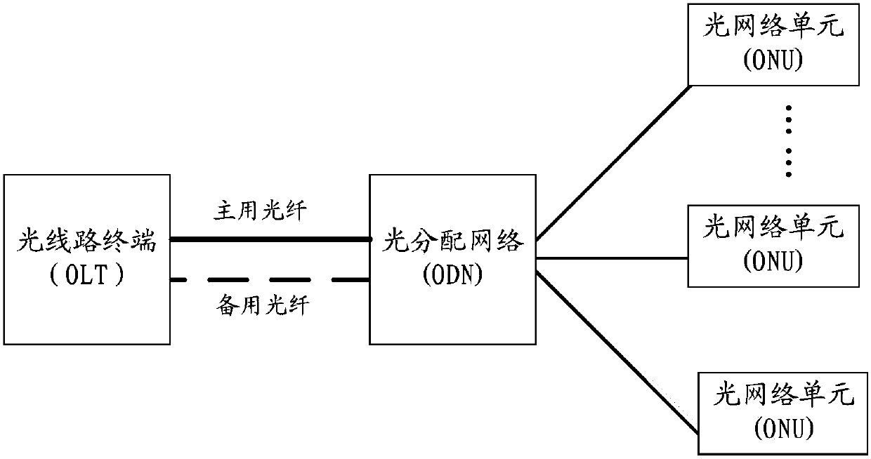
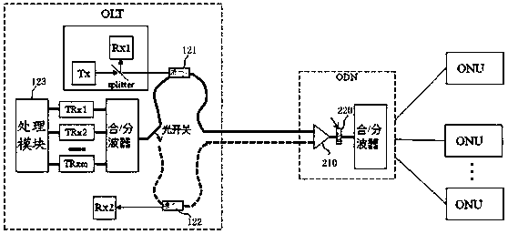
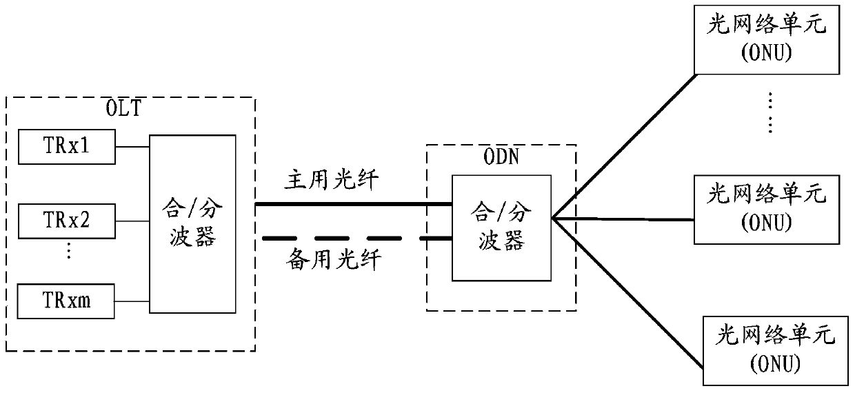
[0043] The embodiment of the present invention provides a passive optical network delay compensation device, method and passive optical network, which can compensate the transmission delay of the main and backup backbone optical fibers in real time, so as to meet the transmission delay requirements of the front-end backhaul for PON , which will be described in detail below.

[0044] The following will clearly and completely describe the technical solutions in the embodiments of the present invention with reference to the accompanying drawings in the embodiments of the present invention. Obviously, the described embodiments are only some, not all, embodiments of the present invention. Based on the embodiments of the present invention, all other embodiments obtained by those skilled in the art without creative efforts fall within the protection scope of the present invention.

[0045] The terms "first", "second", "third", "fourth", etc. (if any) in the description and claims of ...


PUM


Abstract

Disclosed are a delay compensation apparatus and method of a passive optical network, and a passive optical network. The delay compensation apparatus comprises: a first component deployed on an OLT side and a second component deployed on an ODN side. The first component comprises a probe-light sending unit and a delay processing unit. The probe-light sending unit is configured to send a probe signal to an active feeder fiber or a standby feeder fiber. The second component comprises a splitter and a reflection component. A first branch end of the splitter is coupled with the active feeder fiber, a second branch end is coupled with the standby feeder fiber, and a public end is coupled with a public end of the ODN by using the reflection component. The delay processing unit is configured to obtain information about a first time when a first optical signal arrives at the OLT and information about a second time when a second optical signal arrives at the OLT, and performing delay compensation on data transmission of the OLT. By means of embodiments of the present invention, transmission delays of active and standby feeder fibers can be compensated in real time, so as to meet a transmission delay requirement of front-end backhaul on a PON.

Description

technical field [0001] The invention relates to the field of optical fiber communication, in particular to a time delay compensation device and method of a passive optical network and a passive optical network. Background technique [0002] Among various broadband access technologies, PON (Passive Optical Network, Passive Optical Network) has become a strong competitor of the next-generation broadband access network due to its advantages of large capacity, long transmission distance, low cost, and full service support. [0003] figure 1 It is a common structure of the existing PON, including OLT (optical line terminal, optical line terminal) at the central office, ODN (optical distribution network, optical distribution network) and ONU (optical network unit, optical network unit) at the user end. The so-called passive means that the ODN does not contain any active electronic devices and electronic power sources, and is entirely composed of passive devices such as optical sp...

Claims


Application Information

Patent Timeline
Patent Type & Authority Patents(China)
IPC IPC(8): H04Q11/00H04J14/02
CPCH04B10/07H04Q11/00
Inventor 徐之光
Owner HUAWEI TECH CO LTD
Why Eureka
Try Eureka