Workpiece clamping and detecting tool

A technology for detecting tooling and workpieces, applied in measuring devices, instruments, using wave/particle radiation, etc., can solve problems such as complex detection process

Inactive Publication Date: 2017-04-05
张宗发
View PDF0 Cites 0 Cited by
  • Summary
  • Abstract
  • Description
  • Claims
  • Application Information

AI Technical Summary

Problems solved by technology

[0003] In order to solve the defect that the detection process is relatively complicated, the present invention provides a workpiece clamping and detection tooling

Method used


Image

  • Workpiece clamping and detecting tool

Examples


Embodiment 1

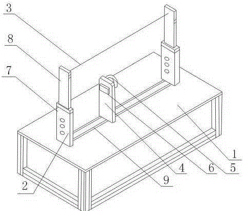
[0016] Such as figure 1 As shown, a workpiece clamping and testing tooling includes a workbench 1, an adjustment seat 2 arranged on the left and right sides of the workbench 1, a detection wire harness 3 connected to the adjustment seats 2 on both sides, and a detection wire harness 3 arranged on the adjustment seat 2 and the detection wire harness 3 The fluctuation sensor at the joint; also includes the splint 4 arranged between the left and right sides adjustment seat 2, the suction cup 5 that is arranged on the splint 4 and the motor 6 connected with the suction cup 5; the adjustment seat 2 includes an upper end opening and is empty The base 7 of the cavity structure, the connecting rod 8 that runs through the opening of the upper end of the base 7 is slidably arranged in the base 7; the base 7 and the connecting rod 8 are respectively provided with uniform holes, and the base 7 and the connecting rod 8 pass through the holes on the base 7 and the connecting rod 8 at the sam...

Embodiment 2

[0019] On the basis of Embodiment 1, this embodiment further includes two moving grooves 9 arranged in parallel on the worktable 1 , and the splint 4 is slidably arranged on the moving grooves 9 .

[0020] The splint 4 can slide on the moving groove 9, so that the splint 4 can select a suitable position according to the thickness of the workpiece to be tested, so as to achieve the best test effect.


PUM


Abstract

The invention provides a workpiece clamping and detecting tool, comprising: a work station, adjusting bases arranged at the left side and the right side of the work station, detection wire harnesses in connection with the adjusting bases at the two sides and fluctuation sensors arranged at the connection parts between the adjusting bases and the detection wire harnesses. The tool also comprises a clamping board arranged between the adjusting bases at the left side and the right side, a sucker of a rotation device on the clamping board and a motor in connection with the sucker. Each adjusting base comprises an upper end opening, an empty cavity structured base, and a connection rod penetrating the upper end opening and arranged on the base in a sliding manner. According to the invention, the sucker and the motor are arranged in such a manner that a workpiece can be made to rotate. When the angles of the workpiece touch the detection wire harnesses, it is possible to determine the flattening degree at the circumference of the workpiece through the observation of the ripple signals generated on the processor in a relatively convenient manner.

Description

technical field [0001] The invention relates to a tooling, in particular to a workpiece clamping and testing tooling. Background technique [0002] When detecting the flatness around the workpiece, the traditional method uses a single detection of the flatness of one side. This method can only show the flatness of one side, but cannot reflect the flatness relationship between the four sides, and the detection process is also more complicated. . Contents of the invention [0003] In order to solve the defect that the detection process is relatively complicated, the present invention provides a workpiece clamping and detection tool. [0004] Technical scheme of the present invention is as follows: [0005] A workpiece clamping and detection tooling, including a workbench, adjustment seats arranged on the left and right sides of the workbench, a detection wire harness connected to the adjustment seats on both sides, and a fluctuation sensor arranged at the connection betwee...

Claims


Application Information

Patent Timeline
Patent Type & Authority Applications(China)
IPC IPC(8): G01B15/08
Inventor 张宗发
Owner 张宗发
Why Eureka
Try Eureka