Air bearing spindle with speed measurement function

An electric spindle and functional technology, applied in the direction of manufacturing tools, measuring/indicating equipment, large fixed members, etc., can solve the problem that the performance of the air-floating shaft core is difficult to meet the high standard requirements, the measurement of the electric spindle is even more difficult, and the power cannot meet the requirements and other problems, to achieve the effect of reasonable air flotation air circuit design, good heat dissipation effect and high rotation stability

Active Publication Date: 2017-04-19
GUANGZHOU HAOZHI ELECTROMECHANICAL
View PDF9 Cites 8 Cited by
  • Summary
  • Abstract
  • Description
  • Claims
  • Application Information

AI Technical Summary

Problems solved by technology

[0004] The speed of the existing air-floating high-speed electric spindle is generally less than 200,000 rpm, mainly because the performance of the air-floating shaft core, bearings, motors and other components is still difficult to meet high standards.
At the same time, in the case of ultra-high speed, it is even more difficult to measure the speed of the electric spindle
Although foreign countries have developed electric spindles with a speed of more than 200,000 rpm, the diameter of the shaft is relatively small, so it can only be used to process micro-holes, and the parameters such as power cannot meet the status quo.

Method used


Image

  • Air bearing spindle with speed measurement function
  • Air bearing spindle with speed measurement function
  • Air bearing spindle with speed measurement function

Examples


Embodiment Construction

[0043] Below, in conjunction with accompanying drawing and specific embodiment, the present invention is described further:

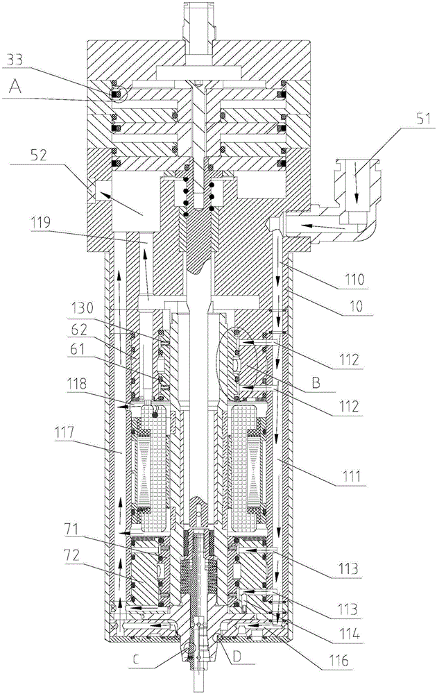
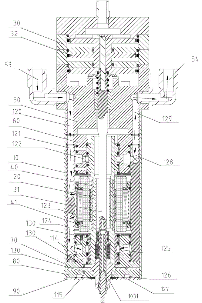
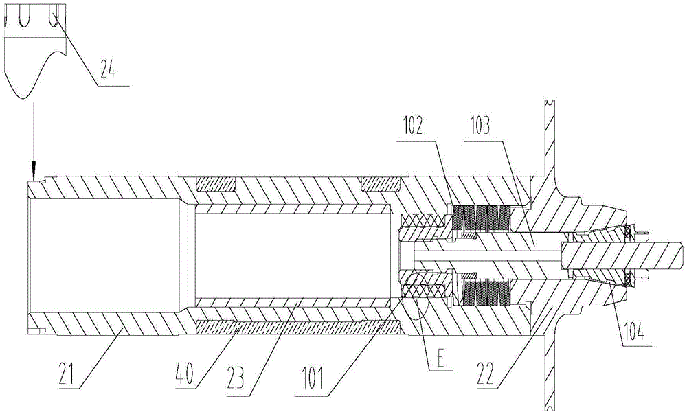
[0044] Such as Figure 1-11 As shown, an air-floating electric spindle with speed measuring function includes a body 10, a shaft core assembly 20, a power assembly, an aluminum water jacket 50, a cylinder 30, an upper bearing assembly 60, a lower bearing assembly 70, a thrust bearing assembly 80 and a cover The plate assembly 90; the body 10 is a cavity structure, and the main air inlet passage 111 and the return air passage 117 are respectively arranged in the wall surface of the body 10 along the axial direction; the shaft core assembly 20 is arranged in the body 10, which includes a chuck section 22 and shaft section 21; (see image 3) The chuck section 22 and the rotating shaft section 21 are both hollow structures; the chuck section 22 is provided with a shaft shoulder; the upper part of the rotating shaft section 21 is provided with a number of s...


PUM


Abstract

The invention discloses an air bearing spindle with a speed measurement function. The air bearing spindle with the speed measurement function comprises a body, a spindle core assembly, a power assembly, an aluminum water jacket, a cylinder, an upper bearing assembly, a lower bearing assembly, a thrust bearing assembly and a cover plate assembly, wherein the body is of a cavity structure; the spindle core assembly comprises a rotating shaft section and a chuck section; the rotating shaft section sleeves the chuck section; speed measurement grooves are formed in the rotating shaft section; the power assembly comprises a copper bordered rotor and a stator assembly; the copper bordered rotor is inlaid into the rotating shaft section; the stator assembly is arranged in the body and is opposite to the copper bordered rotor; the upper bearing assembly is arranged on the upper part of the rotating shaft section; speed measurement sensors are arranged on the upper part of the upper bearing assembly and correspond to the speed measurement grooves; the lower bearing assembly is arranged on the lower part of the rotating shaft section; the thrust bearing assembly is arranged on the chuck section; the cover plate assembly is arranged at the bottom of the thrust bearing assembly; the aluminum water jacket is arranged on the top of the upper bearing assembly; and the cylinder is arranged on the top of the aluminum water jacket. The air bearing spindle with the speed measurement function is easy to process, simple in structure and good in heat dissipation effect, and runs stably.

Description

technical field [0001] The invention relates to the technical field of processing equipment, in particular to an air-floating electric spindle with a speed measuring function. Background technique [0002] With the demand for economic development and technological take-off, more and more new technologies are emerging, and the machining industry is also emerging, especially the technological innovation of the leading electric spindle industry is very obvious. The electric spindle is a new technology that integrates the machine tool spindle and the spindle motor. [0003] In the production process of PCB board, it is inevitable to use electric spindle. With the miniaturization of electronic components and the diversification of various electrical functions, the integration of PCB boards is getting higher and higher. The tiny holes (Φ0.05-Φ0.2mm) on the PCB are becoming more and more dense. At present, the number of non-through holes in multilayer boards has reached 100 / cm 2...

Claims


Application Information

Patent Timeline
Patent Type & Authority Applications(China)
IPC IPC(8): B23B19/02B23Q17/00
CPCB23Q1/70B23Q17/00
Inventor 吴魁雷群汤秀清
Owner GUANGZHOU HAOZHI ELECTROMECHANICAL
Why Eureka
Try Eureka