Electromagnetic coil with velocity measurement function

An electromagnetic coil and function technology, which is applied in the measurement device, engine cooling, linear/angular velocity measurement, etc., can solve the problems of single function of electromagnetic coil and no speed measurement function, and achieve the effect of simple and compact structure

Active Publication Date: 2012-11-14
NANJING AOLIAN AE&EA
View PDF0 Cites 0 Cited by
  • Summary
  • Abstract
  • Description
  • Claims
  • Application Information

AI Technical Summary

Problems solved by technology

However, the existing electromagnetic coil has a single function and does not have a speed measuring function.

Method used


Image

  • Electromagnetic coil with velocity measurement function
  • Electromagnetic coil with velocity measurement function
  • Electromagnetic coil with velocity measurement function

Examples


Embodiment Construction

[0018] In order to make the technical means, creative features, goals and effects achieved by the present invention easy to understand, the present invention will be further described below in conjunction with specific embodiments.

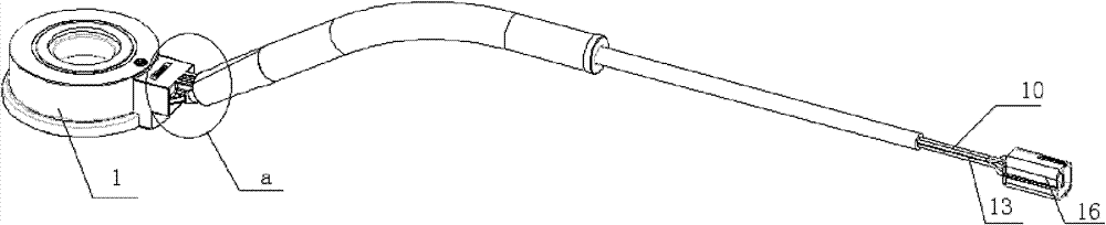
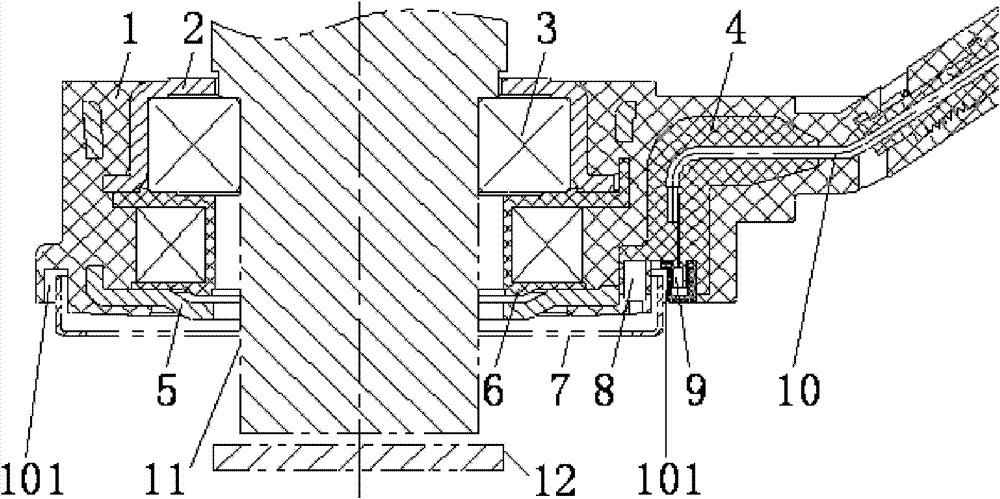
[0019] see figure 1 , figure 2 and image 3 , the present invention comprises a magnet 8, a hall sensor 9, a five-pin plug 16 connected to an automobile ECU, an outer shell 1 and a bearing base 2 installed in the outer shell 1, a bearing 3 interference-fitted in the bearing base 2, The coil 6 and the coil base 5 for installing the coil 6; and the bearing base 2, the bearing 3, the coil 6 and the coil base 5 are coaxially installed in the outer shell 1, and the coaxial installation will reduce the difficulty of subsequent installation of other parts.

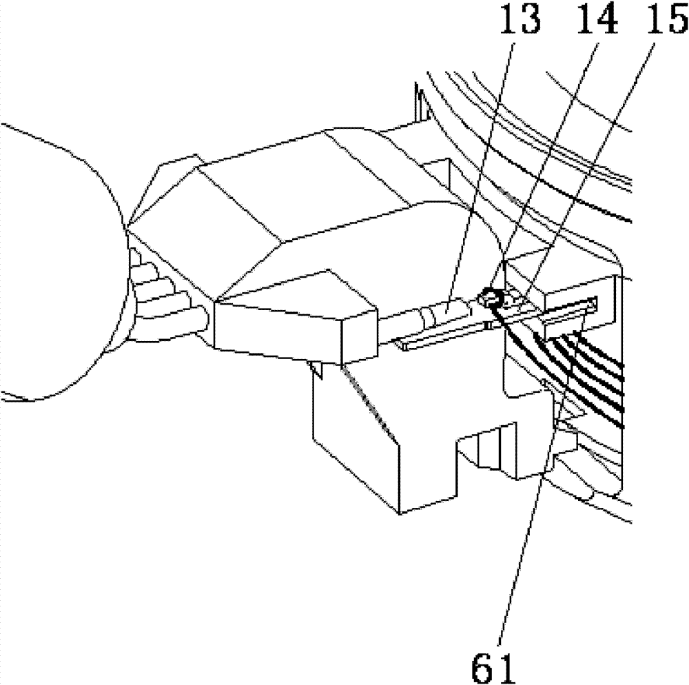
[0020] Copper enameled wire 14 and two symmetrical coil grooves 61 are wound on the coil 6 .

[0021] The three pins of the Hall sensor 9 are respectively connected to the five-pin plug 16 throug...


PUM


Abstract

The invention discloses an electromagnetic coil with a velocity measurement function. The electromagnetic coil comprises an outer shell, a bearing base, a bearing, a coil and a coil base, wherein the bearing base, the bearing, the coil and the coil base are arranged in the outer shell; the coil is provided with an enamelled wire and two coil grooves; the electromagnetic coil also comprises a magnet, a Hall sensor and a five-core plug; three pins of the Hall sensor are respectively connected with the five-core plug through Hall sensor leads; the magnet, the Hall sensor and the Hall sensor leads are fixed with the inner wall of the outer shell into a whole through hot melt glue; an outer shell groove capable of holding a velocity measurement disc is arranged between the magnet and the Hall sensor; and cold-pressed terminals connected with two ends of the enamelled wire are arranged in the coil grooves and are also connected with the five-core plug through coil leads. The electromagneticcoil has a simple and compact structure and the velocity measurement function and is suitable for large batch production.

Description

technical field [0001] The invention relates to an electromagnetic coil, in particular to an electromagnetic coil with speed measuring function, and belongs to the technical field of automobile cooling. Background technique [0002] Since the country implemented the National III and National IV standards, energy conservation, consumption reduction, and emission reduction have become the main theme of the development of the automobile industry. As an important part of the engine cooling system, the cooling fan usually consumes 5% to 8% of the engine's energy consumption. From fixed fans, temperature-sensing ring silicon oil clutch-driven fans, to electronically controlled silicon oil clutch-driven fans, fan technology upgrades The replacement has contributed to the improvement of engine efficiency and the realization of energy saving and emission reduction. In order to achieve precise control, the electronically controlled silicone oil clutch is currently the most ideal choi...

Claims


Application Information

Patent Timeline
Patent Type & Authority Patents(China)
IPC IPC(8): F01P7/04G01P3/481
Inventor 池敦峰孙荣飞周旭兵
Owner NANJING AOLIAN AE&EA
Why Eureka
Try Eureka