Driving axle and vehicle

A drive axle, drive shaft technology, applied in the field of vehicles, can solve problems such as harsh and complex working conditions

Inactive Publication Date: 2017-04-19
湖南中联重科车桥有限公司
View PDF9 Cites 2 Cited by
  • Summary
  • Abstract
  • Description
  • Claims
  • Application Information

AI Technical Summary

Problems solved by technology

However, as the vehicle load increases and the working conditions become harsh and complex, how to deal

Method used


Image

  • Driving axle and vehicle
  • Driving axle and vehicle
  • Driving axle and vehicle

Examples


Embodiment Construction

[0030] Specific embodiments of the present invention will be described in detail below in conjunction with the accompanying drawings. It should be understood that the specific embodiments described here are only used to illustrate and explain the present invention, and are not intended to limit the present invention.

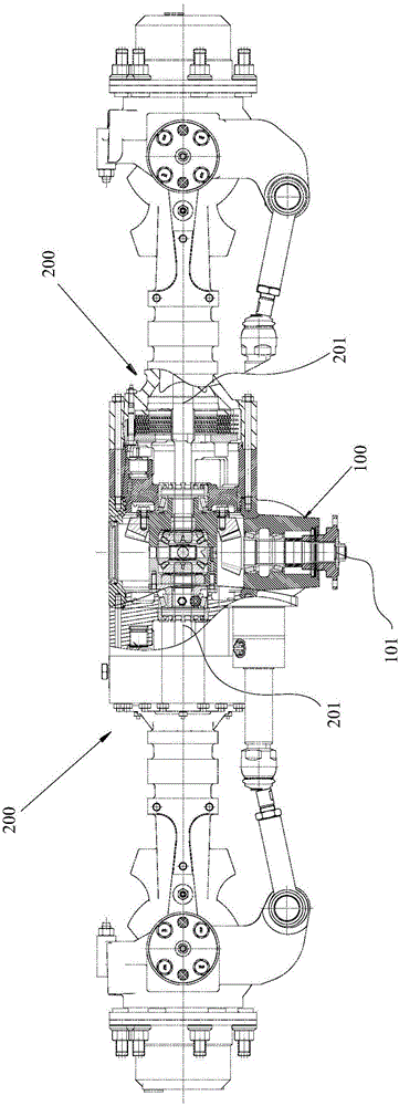
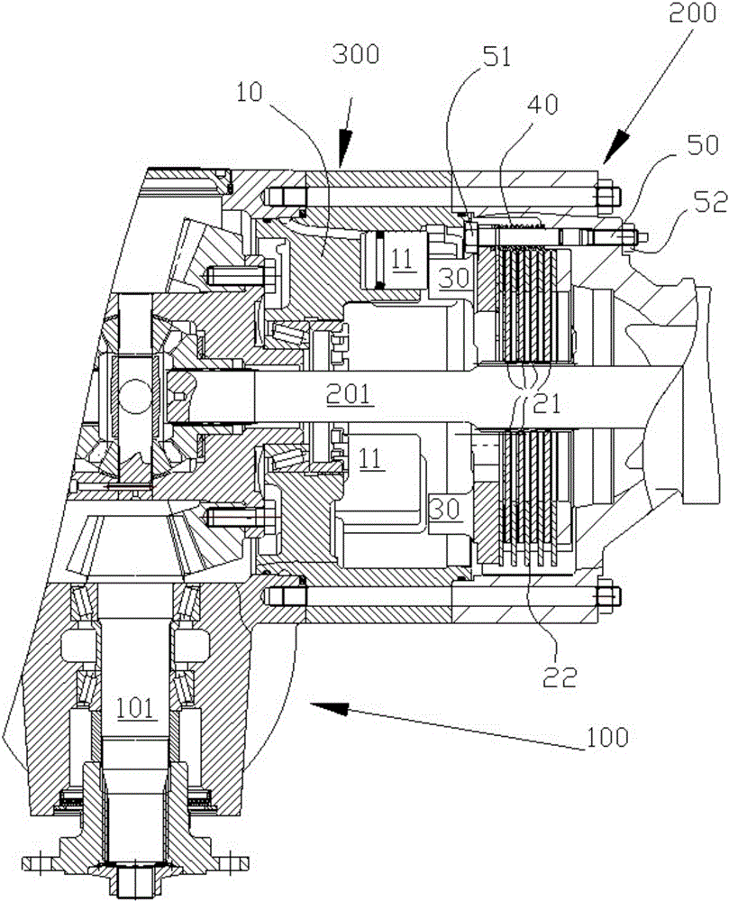
[0031] like figure 1 As shown, the present invention provides a drive axle, which includes: a drive shaft assembly 100, the drive shaft assembly 100 has a drive shaft 101; a pair of half-shell assemblies 200, the pair of half-shell assemblies 200 have A pair of half-shafts 201, the drive shaft assembly 100 is assembled with the pair of half-shell assemblies 200, and the drive shaft 101 and the half-shaft 201 are all connected by transmission; wherein, the drive axle also includes a pair of brakes 300, and the pair of brakes 300 are respectively It is arranged at the end of the half-shell assembly 200 adjacent to the drive shaft assembly 100 , and can directly a...


PUM


Abstract

The invention relates to a driving axle. The driving axle comprises a driving shaft assembly (100) and a pair of shell half assemblies (200). The driving shaft assembly (100) is provided with a driving shaft (101). The pair of shell half assemblies (200) are provided with a pair of shaft halves (201). The driving shaft assembly (100) is assembled to the pair of shell half assemblies (200), and the driving shaft (101) is in transmission connection with each shaft half (201). The driving axle further comprises a pair of brakes (300). The brakes (300) are arranged at the ends, adjacent to the driving shaft assembly (100), of the shell half assemblies (200) correspondingly, and each brake (300) can directly apply braking force to the corresponding shaft half (201). For a driving axle which is not suitable for drum type braking and caliper braking, the braking function can also be achieved reliably and conveniently.

Description

technical field [0001] The invention relates to the field of vehicles, in particular to a drive axle and a vehicle including the drive axle. Background technique [0002] For vehicles, in order to improve certain performances of the vehicle, the front axle needs to be designed as a steering drive axle. Its function includes providing driving force for the driving wheels, and at the same time, it is combined with a steering mechanism to realize the steering function of the vehicle. [0003] For vehicles that are not suitable for drum brakes and caliper brakes, the wet brakes of the rear axle are often used to provide all the braking of the vehicle, while the steering drive axle is not braked. However, as the vehicle load increases and the working conditions become severe and complex, how to deal with the more demanding vehicle braking requirements has become an urgent technical problem to be solved. Contents of the invention [0004] The purpose of the present invention is...

Claims


Application Information

Patent Timeline
IPC IPC(8): B60T1/06
CPCB60T1/062
Inventor 许名苟万永杰杨玉
Owner 湖南中联重科车桥有限公司
Why Eureka
Try Eureka