Brake actuating apparatus using an electric motor

A technology of brakes and brake pads, applied in the direction of brakes, brake types, brake transmissions, etc., can solve problems such as difficult manufacturing and assembly, complex structure, and increased production costs

Inactive Publication Date: 2007-04-04
WHEEL CORP
View PDF1 Cites 3 Cited by
  • Summary
  • Abstract
  • Description
  • Claims
  • Application Information

AI Technical Summary

Problems solved by technology

Therefore, its disadvantage is that the structure of the device is complicated, it is difficult to manufacture and assemble the device, and the production cost increases

Method used


Image

  • Brake actuating apparatus using an electric motor
  • Brake actuating apparatus using an electric motor
  • Brake actuating apparatus using an electric motor

Examples


Embodiment Construction

[0040] Hereinafter, preferred embodiments of the present invention will be described in detail with reference to the accompanying drawings.

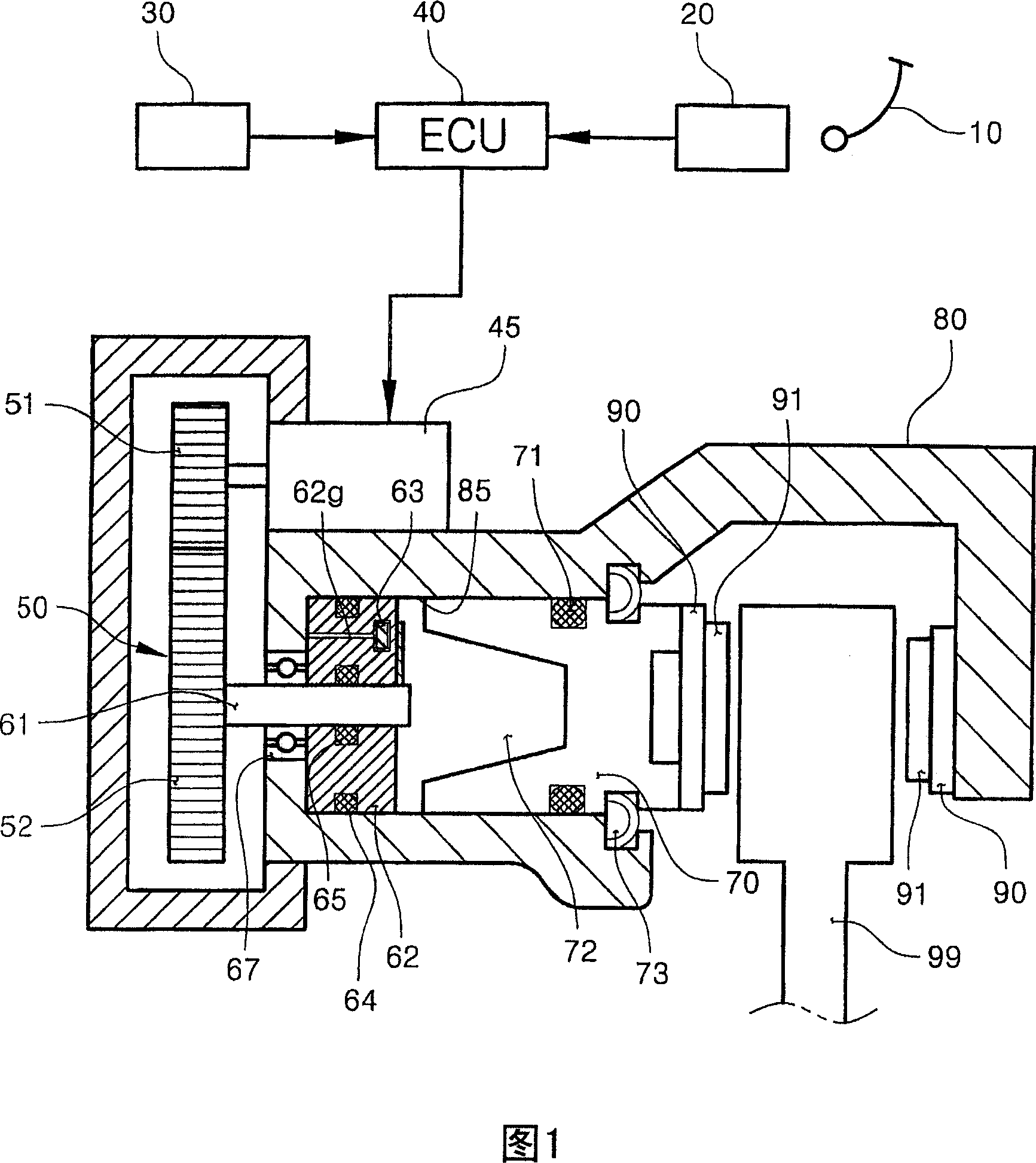
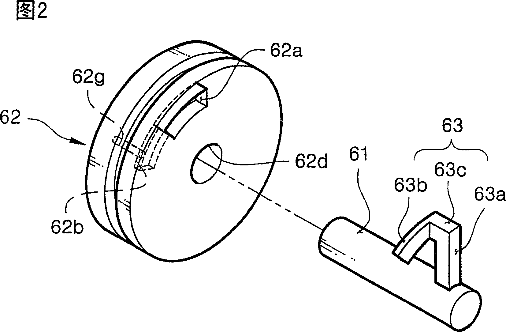
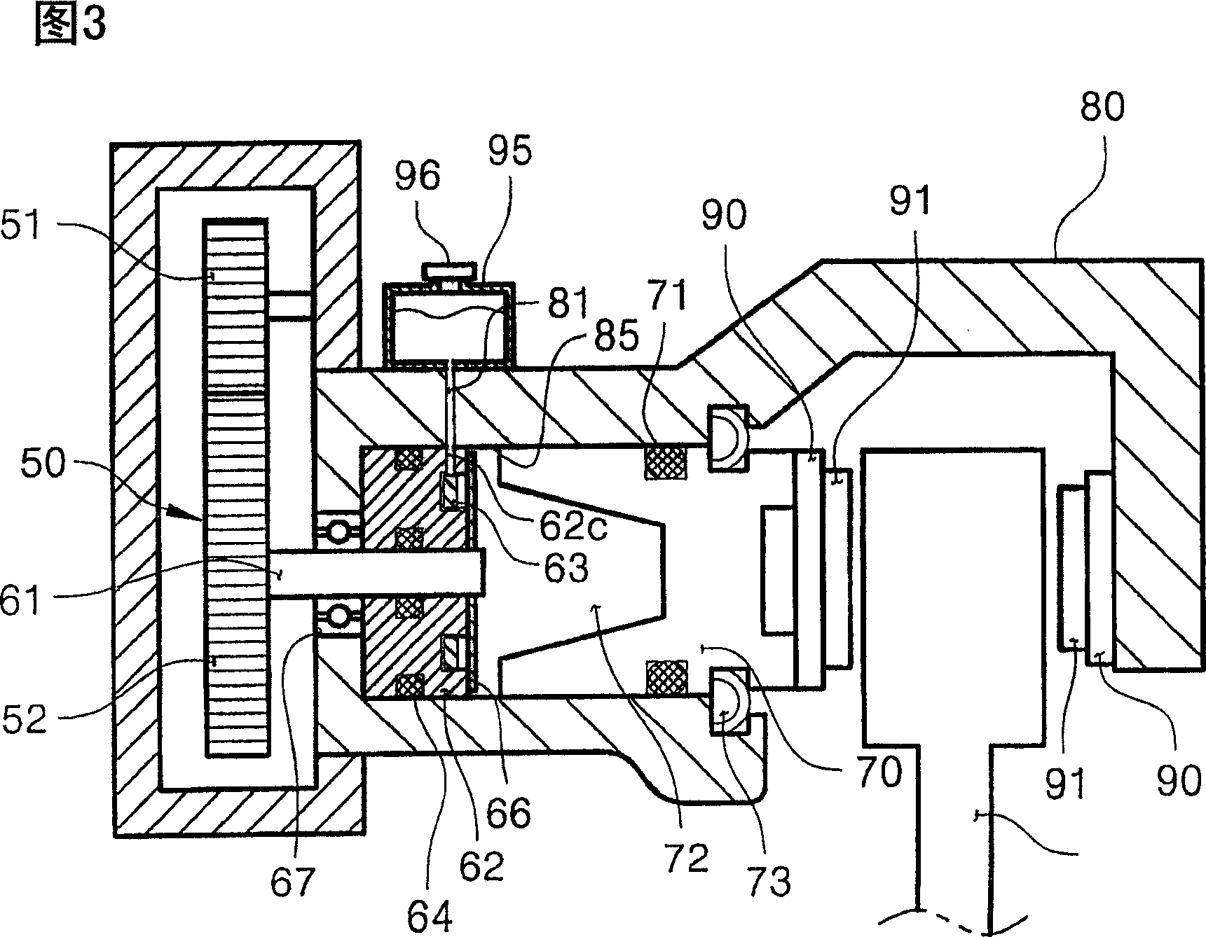
[0041] FIG. 1 is a schematic diagram of a brake device according to an embodiment of the present invention, and FIG. 2 is a perspective view of an embodiment of a housing and a fluid pressurizing component of the brake device shown in FIG. 1, the housing and fluid components Separated from each other.

[0042] As shown in FIG. 1, the brake device of this embodiment includes: a caliper body 80 with a cylinder 85; a motor 45 fixed to the caliper body 80; a pressure piston 70 installed in the cylinder 85; and a housing 62, which is separated from the pressure piston 70 by a predetermined distance in the back, and is fixedly installed on the cylinder 85 to maintain airtightness with the inner circumference of the cylinder 85; the rotating shaft 61 installed in the center of the housing 62 is received by The rotating force transmitted by the moto...


PUM


Abstract

A brake actuating apparatus includes a caliper body with a cylinder. An electric motor is fixed to the caliper body. A piston is installed in the cylinder. A plug and a rotational shaft are installed in the cylinder to be rotated by the motor. A head is attached to the rotational shaft and the plug defines a fluid-receiving space. The rotation of head varies the volume of a fluid contained in the fluid-receiving space, thereby moving the piston.

Description

Technical field [0001] The present invention relates to a braking device using a motor, and more specifically, to a braking device capable of realizing a braking function without converting the rotational motion of the motor into linear motion. That is, the present invention relates to a brake device having a fluid pressurizing member that rotates by receiving the rotational force of a motor to pressurize the fluid contained in the cylinder of the caliper and thereby push the piston of the caliper. Background technique [0002] Generally, the conventional hydraulic brake device includes a hydraulic circuit, in which the pedal pressure generated by the driver's stepping on the pedal is increased in the master cylinder and the multiplier, and then transmitted to the brake device installed on each wheel through a liquid pipe. The disadvantage of traditional hydraulic braking is that braking cannot be achieved if the fluid pipe is damaged. It takes a lot of time to transmit the pedal...

Claims


Application Information

Patent Timeline
Patent Type & Authority Applications(China)
IPC IPC(8): B60T13/74F16D65/14
CPCF16D2127/04F16D2125/36F16D65/18B60T13/745F16D2123/00F16D2121/14F16D65/0075F16D2121/24F16D2125/10F16D2125/48B60T8/326F21S8/085F21V7/0033F21V7/22F21W2131/103
Inventor 赵韩龙
Owner WHEEL CORP
Why Eureka
Try Eureka