Spring-loaded tensioning device for speed limiting steel wire rope

A technology for tensioning devices and steel wire ropes, applied in the field of tensioning devices, can solve problems such as inability to adjust sensitively and provide insufficient and accurate guidance

Active Publication Date: 2017-04-19
비투르홀딩게엠베하
View PDF7 Cites 4 Cited by
  • Summary
  • Abstract
  • Description
  • Claims
  • Application Information

AI Technical Summary

Problems solved by technology

Existing tensioning devices that work with spring tension do not provide sufficiently accurate guidance and / or are sensitively adjustable in terms of their pretension

Method used


Image

  • Spring-loaded tensioning device for speed limiting steel wire rope
  • Spring-loaded tensioning device for speed limiting steel wire rope
  • Spring-loaded tensioning device for speed limiting steel wire rope

Examples


no. 1 example

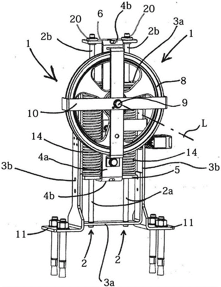
[0038] The core part of the tensioner is the main frame, which consists of two horizontal sections 3a and two vertical sections 3b, see figure 2 . This frame, which is usually completely closed on all sides, actually constitutes an imaginary cuboid which is open on its two large faces. The main frame is ideally made of flat steel, which is bent by 90° where necessary. The main frame forms an annular cage for the spring element 14 .

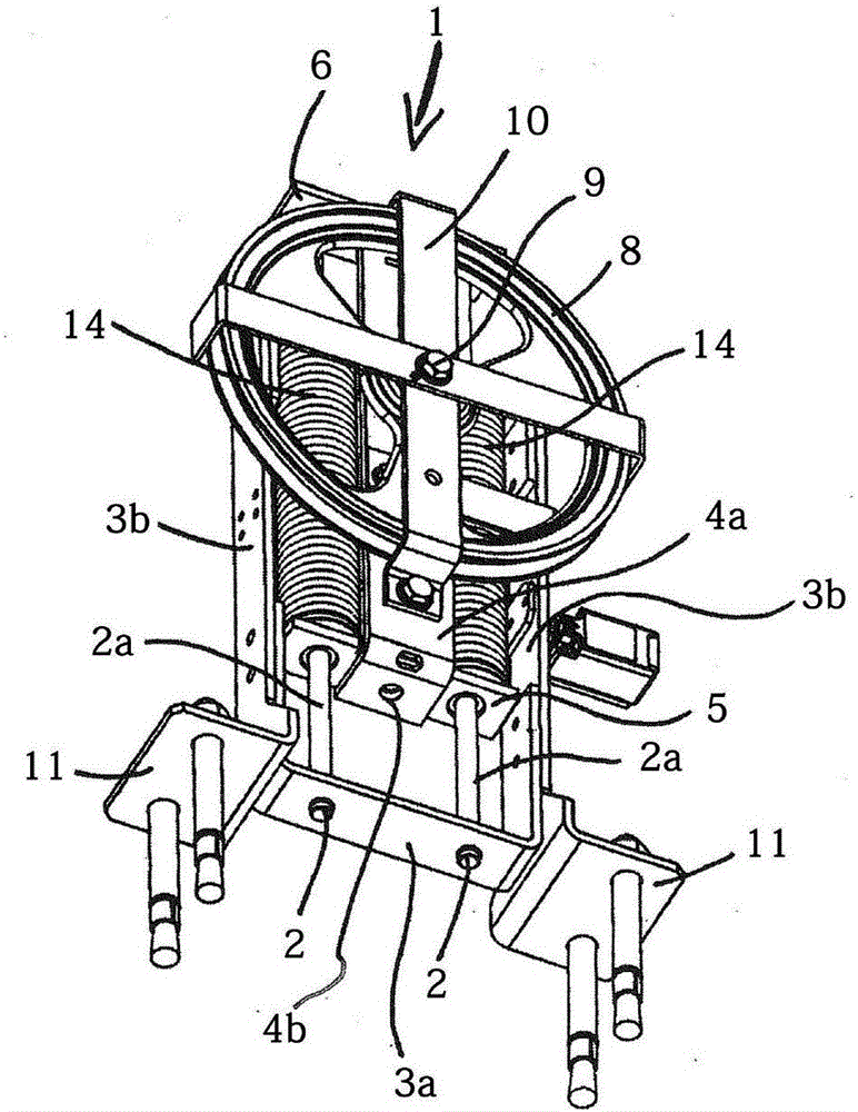
[0039] At least two guide posts 2 are fixed on the lower horizontal part 3a of the main frame, preferably with the help of threads or, less preferably, with the help of corresponding welds or spots. These two guide columns traverse the inner space of the main frame 3a, 3b, pass through two openings in the upper horizontal part 3a of the main frame and protrude from the main frame above the main frame, see image 3 and Figure 4 . In this way, the guide post 2 constitutes a first guide post part 2a in the area enclosed by the main frame and a...

no. 2 example

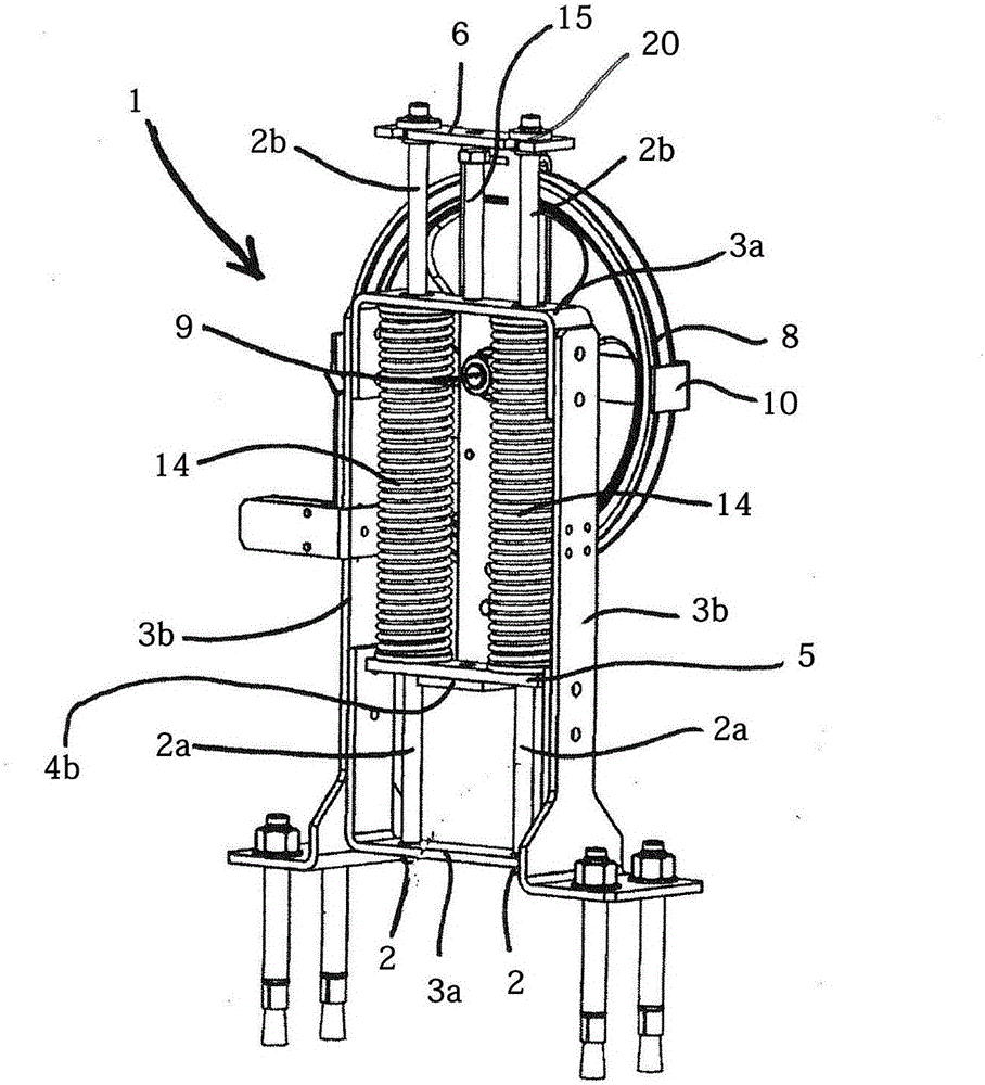
[0051] The second embodiment differs from the first embodiment only in that it is not intended to be fitted on the bottom of the stairwell, but is preferably fixed on the lower end of the guide rail with the aid of the guide rail bracket, ie for wall mounting. Based on this, the statements regarding the first embodiment also apply to the second embodiment, so that reference can be made thereto.

[0052] to combine Figure 6 It can be clearly seen that the feet 11 are omitted in this exemplary embodiment. Instead, the rail holder 12 is fixed, preferably screwed, to the main frame 3a, 3b. The rail holder preferably has elongated holes or single holes, which are arranged closely one after the other and intersect each other laterally, in order to be able to be fastened with the aid of various rail fixing clips for wall mounting of the rail.

[0053] Additionally, combined with Figure 6 It can also be clearly seen that another characteristic, that is, it can also be realized in...

no. 3 example

[0057] Figure 7 and Figure 8 A third embodiment is shown. The third embodiment corresponds almost completely to the first embodiment, so the expressions related to the first embodiment are also used for the third embodiment, as long as no difference is obtained from the following differences.

[0058] The third exemplary embodiment differs from the first exemplary embodiment in that each spring element 14 (here also designed as a helical compression spring) is threaded on a guide tube 19 . Each guide tube 19 itself is threaded on the guide post 2 . The individual guide tubes 19 are preferably dimensioned in such a way that they completely traverse the area enclosed by the main frame 3a, 3b and preferably rest against the upper and lower vertical parts 3b of the main frame, preferably correspondingly with centering bushes 21 provided. The outer diameter of the guide tube 19 is preferably 1 mm to 2 mm smaller in size than the inner diameter of the spring element 14 .

[00...


PUM


Abstract

The invention relates to a tensioning device for a speed limiting steel wire rope for an elevator. The tensioning device is provided with a spring tensioning mechanism for tightening a guide pulley for the speed limiting steel wire rope, wherein the spring tensioning mechanism consists of at least two guide columns and a sliding frame; a corresponding spring element is threaded on the guide column and each guide column is secured by a main frame in such a way that the first guide column section is completely within the region encompassed by the main frame and the second guide column section is situated above the main frame outside the region encompassed by the main frame; the sliding frame is provided with a guide pulley mounted on the sliding frame rotatably; the sliding frame is supported in sliding fashion on the guide columns by means of two yokes; the lower yoke of a slider runs on the first guide column section and forms an abutment for the spring elements on the second guide column section; and the upper yoke of the sliding frame travels on the second guide column section and preferably comes to a stop against an adjustable spring travel limiter, wherein the spring elements are supported at the other end against the upper horizontal section of the main frame.

Description

technical field [0001] The invention relates to a tensioning device for speed-limiting steel ropes of elevators according to the preamble of claim 1 . Background technique [0002] Elevators, at least until now, have generally been provided with conventional speed-limiting ropes. [0003] This is a continuous wire rope which circulates at least via upper and lower guide pulleys. Typically, the speed-limiting wire rope is fastened to an arm mounted on the side of the car for triggering the stopping and braking of the car. In this way, the speed-limiting wire rope is carried by the car and thus driven. [0004] Typically, the upper guide pulley is connected to the original governor. If this guide wheel turns too fast, it means that the car has exceeded the maximum permissible speed and is braked or even has to be stopped. Thus the overspeed governor will decelerate the guide wheels belonging to it. The speed-limiting rope becomes sluggish and lags behind the elevator, in ...

Claims


Application Information

Patent Timeline
Patent Type & Authority Applications(China)
IPC IPC(8): B66B5/04
CPCB66B5/044B66B5/04B66B5/18
Inventor 勒内·霍尔茨卡尔·科里纳利奥波德·拉什巴赫
Owner 비투르홀딩게엠베하
Why Eureka
Try Eureka