Efficient oil water separation device

An oil-water separation device and high-efficiency technology, applied in the fields of hydrocarbon oil dehydration/demulsification, petroleum industry, processing of hydrocarbon oil, etc. The effect of high degree of automation and strong adaptability to low temperature

Inactive Publication Date: 2017-04-19
JIANGSU HENGDA MACHINERY MFG
View PDF4 Cites 4 Cited by
  • Summary
  • Abstract
  • Description
  • Claims
  • Application Information

AI Technical Summary

Problems solved by technology

For example, there are many waste oil recovery devices on the market, which are cumbersome to operate and have low automation. The existing waste oil recovery devices cannot work normally when encountering ultra-low temperatures, and their applicability to low temperatures is poor.

Method used


Image

  • Efficient oil water separation device

Examples


Embodiment Construction

[0018] The present invention will be further described in detail below in conjunction with the accompanying drawings and specific embodiments.

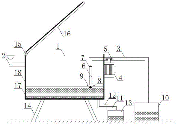
[0019] as attached figure 1 As shown, a high-efficiency oil-water separation device of the present invention includes a box body 1, an input pipe 2, an oil suction pipe 3, a motor 4, an oil discharge impeller 5, a connecting pipe 6, a slider 7, a filter head 8, a floating plate 9, Oil storage tank 10, sewage pipe 11, control valve 12, collection box 13, legs 14, rotating shaft 15, cover 16, heating device 17 and insulation layer 18, wherein the box body 1 has an open upper mouth; wherein the box body 1 The side walls of the tank are respectively provided with an input pipe 2 and an oil suction pipe 3; wherein the oil suction pipe 3 is equipped with an oil discharge impeller 5; wherein the oil discharge impeller 5 is connected with the drive shaft of the motor 4; wherein the connecting pipe 6 is movably connected by a slider 7 Inside ...


PUM


Abstract

The invention relates to an efficient oil water separation device. The efficient oil water separation device comprises a tank body, an input pipe, an oil sucking pipe, a motor, an oil discharge impeller, a connecting pipe, a sliding block, a filter head, a floating plate, an oil storage tank, a blowdown pipe, a control valve, a collection tank and supporting legs, wherein the tank body is provided with an open upper hole; the input pipe and the oil sucking pipe are arranged on the side wall of the tank body; the oil discharge impeller is mounted on the oil sucking pipe; the oil discharge impeller is connected with a driving shaft of the motor; the connecting pipe is movably connected in the oil sucking pipe through the sliding block; the filter head is arranged at the lower end of the connecting pipe; the floating plate is wound and fixed in the position, close to the filter head, of the lower end of the connecting pipe; the outer end part of the oil sucking pipe is connected with the oil storage tank; the bottom of the tank body further communicates with the blowdown pipe; the control valve is arranged on the blowdown pipe; the blowdown pipe communicates with an upper hole of the collection tank; and the supporting legs are further arranged at the bottom of the tank body. The efficient oil water separation device is simple in operation, high in automation degree, good in recycling and separation effect and high in low temperature adaptability.

Description

technical field [0001] The invention relates to the field of mechanical equipment, in particular to a high-efficiency oil-water separation device. Background technique [0002] In the daily life of the oil production team, dirty oil can be seen everywhere. For example, the normal maintenance of the oil field will generate a lot of waste oil. However, with the emphasis on environmental pollution, the treatment of dirty oil has been solved accordingly, and it is no longer limited to random Shuffle. For example, there are a lot of dirty oil recovery devices on the market, which are cumbersome to operate and have a low degree of automation. The existing dirty oil recovery devices can't work normally when they encounter ultra-low temperatures, and their applicability to low temperatures is poor. Contents of the invention [0003] The object of the present invention is to provide a high-efficiency oil-water separation device with simple operation, high degree of automation, goo...

Claims


Application Information

Patent Timeline
Patent Type & Authority Applications(China)
IPC IPC(8): C10G33/00
CPCC10G33/00C10G2300/201
Inventor 陈元庆陈元琳梁尚涛黄旭陈尚雨吴非曹兆明刘丽
Owner JIANGSU HENGDA MACHINERY MFG
Why Eureka
Try Eureka