Electronic cabinet lock capable of being unlocked in electromagnetically driven mode

An electromagnetic drive and electronic lock technology, which is applied to non-mechanical transmission-operated locks, building locks, door/window accessories, etc., can solve the problems of unreasonable design of electromagnet and button locking restrictions, single unlocking method, etc., and achieve anti-theft Good effect and safety, convenient closing, and various unlocking methods

Active Publication Date: 2017-04-19
宁波生久科技有限公司
View PDF5 Cites 3 Cited by
  • Summary
  • Abstract
  • Description
  • Claims
  • Application Information

AI Technical Summary

Problems solved by technology

[0003] In order to overcome the above-mentioned deficiencies, the purpose of the present invention is to provide the field with an electromagnetic drive to open the electronic cabinet lock, so as to solve the unreasonable locking restriction design between the electromagnet and the button in the existing similar products, and the relatively single unlocking method question

Method used


Image

  • Electronic cabinet lock capable of being unlocked in electromagnetically driven mode
  • Electronic cabinet lock capable of being unlocked in electromagnetically driven mode
  • Electronic cabinet lock capable of being unlocked in electromagnetically driven mode

Examples


Embodiment Construction

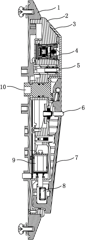
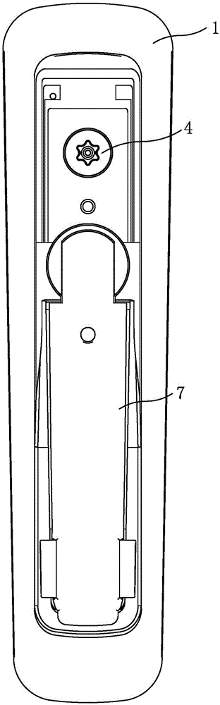
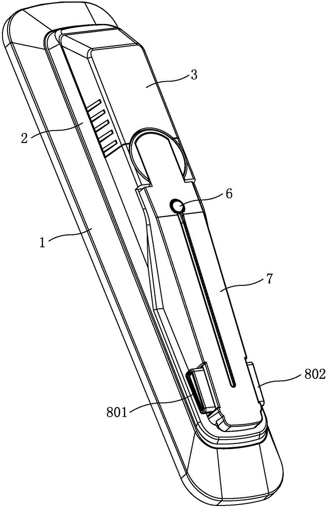
[0018] The structure and use of the present invention will now be further described with reference to the accompanying drawings. like Figure 1-Figure 5 As shown, the electronic cabinet lock includes a base plate 1, a base 2, an electronic lock cylinder assembly 4, a charging port 5, a handle 7, a button 8, an electromagnet assembly 9, and a rotating shaft 10. The base is buckled with the base plate. There are electromagnet switch, handle, electromagnet assembly and rotating shaft. One end of the handle is hinged with one end of the rotating shaft, and the other end of the rotating shaft protrudes from the base and bottom plate. The electromagnet switch is connected with the electromagnet assembly through the line, and the electromagnet assembly is connected with the power supply circuit connect. The electromagnet latch of the electromagnet assembly extends into the other end of the handle, that is, the handle and one end of the base are locked by the electromagnet latch of t...


PUM


Abstract

The invention relates to an electronic cabinet lock capable of being unlocked in an electromagnetically driven mode, which is designed to solve the technical problems that locking limited design between electromagnets and buttons in existing similar products is not reasonable, and an unlocking mode is relatively single. A pedestal of the electronic cabinet lock and a bottom plate of the electronic cabinet lock are locked; one end of a handle is hinged to one end of a rotary shaft; the other end of the rotary shaft extends to the outside of the pedestal and the bottom plate; an electromagnet switch is connected with an electromagnet assembly through a circuit; and the electromagnet assembly is connected with a power supply circuit. The key point of the electronic cabinet lock is that an electromagnet latch of the electromagnet assembly extends into the other end of the handle, i.e., the handle at the end and one end of the pedestal are locked through the electromagnet latch of the electromagnet assembly; the buttons are arranged on the handle at the locked position; the buttons comprise a left button and a right button; latch hooks of the buttons are locked with an inside groove of the pedestal; and the electromagnet latch of the electromagnet assembly is also positioned on the latch hooks of the buttons. The other end of the pedestal is equipped with an electronic lock cylinder assembly; a charging hole is formed in the electronic lock cylinder assembly of the pedestal; and the electronic lock cylinder assembly and the charging hole are sealed in a dustproof cover.

Description

technical field [0001] The invention relates to a high-performance cabinet door lock, belongs to the field of electronic door locks, and is an electromagnetic drive to open an electronic cabinet lock. Background technique [0002] Cabinet locks refer to hardware locks used for metal cabinet doors such as power distribution cabinets, file cabinets, and lockers. Electronic cabinet locks are a general term for electronic locks used in the above cabinets, and generally require strong or weak current to provide unlocking power; according to Its electronic induction method is different, divided into electronic password lock, electronic induction lock and so on. In the electronic door locks currently used for cabinet doors, electromagnets are basically used to control the closing and opening of the mechanical parts to complete the unlocking and locking tasks of the locks. Electronic locks are also used to replace the traditional mechanical combination locks in the locking of some ...

Claims


Application Information

Patent Timeline
Patent Type & Authority Applications(China)
IPC IPC(8): E05B65/52E05B47/02E05B17/00E05B17/22E05B3/00
CPCE05B3/00E05B17/00E05B17/22E05B47/02E05B65/52
Inventor 姚春良
Owner 宁波生久科技有限公司
Why Eureka
Try Eureka