A locking device for random position locking and its minimum force determination method

A locking device and random position technology, applied in friction clamping detachable fasteners, mechanical equipment, connecting components, etc., can solve problems such as high cost, affecting accuracy, complex structure, etc., and achieve cost reduction and simple structure , to create a convenient effect

Inactive Publication Date: 2019-03-05
ZHONGBEI UNIV
View PDF5 Cites 0 Cited by
  • Summary
  • Abstract
  • Description
  • Claims
  • Application Information

AI Technical Summary

Problems solved by technology

Electromagnetic locking is designed using electromagnetic principles. Although it is energy-saving, environmentally friendly, easy to install, and convenient to use, its time response control of magnetic force cannot meet the requirements of milliseconds; although hydraulic locking can be locked and unlocked in a short time, However, the hydraulic oil is easily invaded by pollutants and dust, and the reliability cannot be guaranteed. The temperature change of the hydraulic oil will also affect its accuracy. The layout of various oil circuits makes it much more complicated than the purely mechanical locking mechanism. High cost

Method used


Image

  • A locking device for random position locking and its minimum force determination method
  • A locking device for random position locking and its minimum force determination method
  • A locking device for random position locking and its minimum force determination method

Examples


Embodiment Construction

[0024] In order to make the technical problems, technical solutions and beneficial effects to be solved by the present invention clearer, the present invention will be further described in detail below in conjunction with the accompanying drawings and embodiments. It should be understood that the specific embodiments described here are only used to explain the present invention, not to limit the present invention.

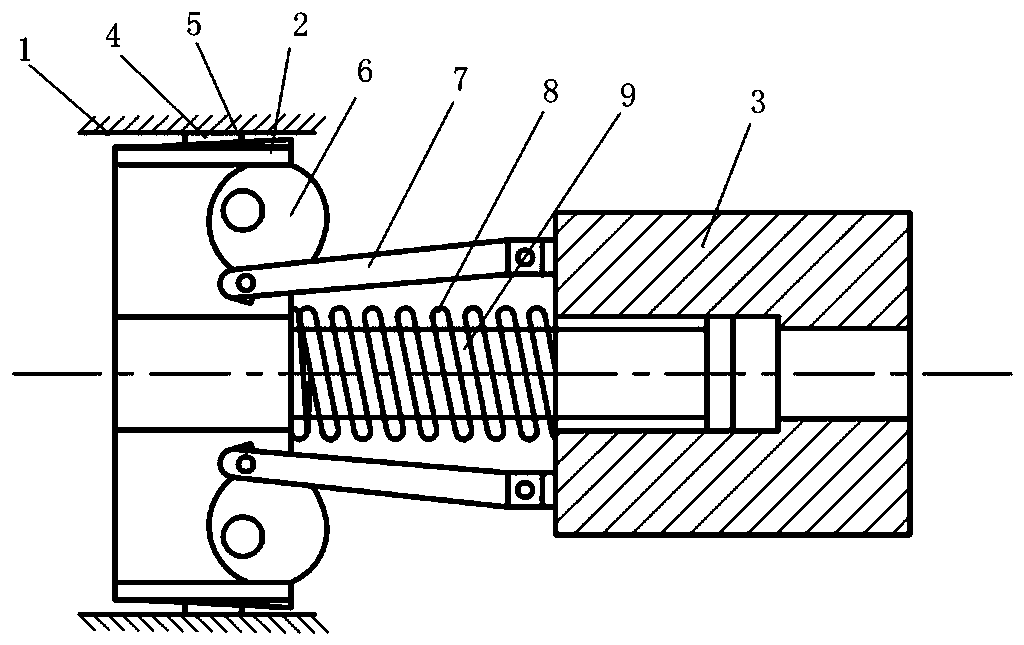
[0025] like figure 1 As shown, a locking device for random position locking and its minimum force determination method, including a fixed hollow lock body 1, a piston 2 slidingly arranged in the hollow lock body, and a moving body set on the piston rod 9 3. The piston 2 is provided with an elastic sheet 5 and an eccentric wheel 6 for driving the elastic sheet. The elastic sheet 5 is provided with a wedging block 4, and the wedging block 4 is arranged between the elastic sheet 5 and the inner wall of the hollow lock body 1. , the eccentric wheel 6 rotates, and the ...


PUM


Abstract

The invention relates to a locking device for random position locking and a method for determining the minimum stress thereof, belonging to the technical field of locking devices. A locking mechanism with simple structure and reasonable design, which realizes locking in random positions by means of eccentric wheels to drive resilient strips and unlocking timely and realizes cycle working with reliable locking, and a method for determining the minimum stress thereof are provided. The technical scheme comprises a fixed hollow locking body and a piston which is slidingly installed inside the hollow locking body, and a moving body which is installed on a piston rod in a sleeved mode; the piston is provided with resilient strips and eccentric wheels for driving the resilient strips; each resilient strip is provided with a wedge block which is installed between the resilient strip and the inner wall of the hollow locking body; the resilient strips are jacked up on the wedge blocks by the rotating eccentric wheels; The locking device is widely used in locking mechanism involved in complex motion.

Description

technical field [0001] The invention relates to a locking device for random position locking and a method for determining the minimum force thereof, belonging to the technical field of locking devices. Background technique [0002] With the development of science and technology, innovation and development are constantly being carried out in various fields, pursuing the development concept of high efficiency, speed, simplicity and environmental protection. Innovative developments are everywhere, locking devices in mechanical structures are a good example. Locking devices are widely used in various mechanical structures, such as aerospace, mining machinery, construction machinery, vehicle engineering and other fields. However, most locking devices can only be locked in a single movement mode at a fixed position at present, such as sleeve locking, snap ring locking, internal expansion locking, cone-disc spring locking and other mechanisms. Although the locking device at any p...

Claims


Application Information

Patent Timeline
Patent Type & Authority Patents(China)
IPC IPC(8): F16B2/14F16B2/18
CPCF16B2/14F16B2/18
Inventor 关世玺喻明让郭嘉瑞孟凡冲王治鑑韩冰郭镇豪董伟康
Owner ZHONGBEI UNIV
Why Eureka
Try Eureka