Consumable cartridge for a plasma arc cutting system

A plasma arc, separation force technology, used in plasma, plasma welding equipment, manufacturing tools, etc., can solve the problem of inability to dissipate and conduct heat from the torch, significant manufacturing costs, and inability to maintain proper alignment and spacing of consumables And other issues

Active Publication Date: 2017-04-19
HYPERTHERM INC
View PDF7 Cites 0 Cited by
  • Summary
  • Abstract
  • Description
  • Claims
  • Application Information

AI Technical Summary

Problems solved by technology

[0003] Known consumables have a number of disadvantages before and during cutting operations
Selecting and installing the correct set of consumables for a particular cutting task can be tedious and time consuming prior to the cutting operation
During operation, current consumables suffer from performance issues such as the inability to effectively dissipate and conduct heat away from the torch and maintain proper alignment and spacing of the consumables
Furthermore, current consumables include very large quantities of expensive materials, such as copper and / or Vespel™, which result in significant manufacturing costs and inhibit their widespread commercialization, production and adoption

Method used


Image

  • Consumable cartridge for a plasma arc cutting system
  • Consumable cartridge for a plasma arc cutting system
  • Consumable cartridge for a plasma arc cutting system

Examples


Embodiment Construction

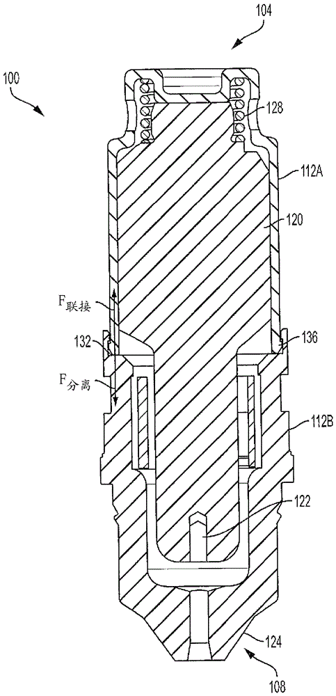
[0028] figure 1 is a cross-sectional schematic illustration of a cartridge 100 for a plasma arc cutting system according to an exemplary embodiment of the present invention. Cartridge 100 has a first end 104 , a second end 108 , and a generally hollow frame 112 having a first section 112A toward first end 104 and a second section toward second end 108 . 112B. Cartridge 100 also includes arc emitter 120 , arc retractor 124 , and resilient element 128 . Arc emitter 120 is located within frame 112 and is translatable relative to frame 112 . As shown, the arc retractor 124 forms part of the frame 112 (eg, at the second end 108 , but may be attached to the frame 112 in some embodiments). The resilient element 128 is in physical communication with the frame 112, such as in direct physical communication with the first section 112A. In some embodiments, resilient member 128 is a contact activated spring element secured to arc emitter 120 . Resilient element 128 may be configured ...


PUM

PropertyMeasurementUnit
lengthaaaaaaaaaa

Abstract

The invention features a replaceable cartridge for a plasma arc torch. The cartridge includes a cartridge body (112) having a first section (112A) and a second section (112B). The first and second sections are joined at an interface (132) to form a substantially hollow chamber. The interface (132) provides a coupling force that secures the first and second sections together. The cartridge also includes an arc constricting member (124) located in the second section; an electrode (120) included within the substantially hollow chamber; and a contact start spring element (128) affixed to the electrode (120). The spring element (128) imparts a separating force that biases the electrode (120) toward at least one of the first section or the second section of the body (112). The separating force has a magnitude that is less than a magnitude of the coupling force.

Description

technical field [0001] The present invention relates generally to the field of plasma arc cutting systems and methods. More specifically, the present invention relates to methods and apparatus for simplifying, optimizing and reducing cutting time and cost through the use of improved consumable cartridges. Background technique [0002] Plasma arc torches are widely used for cutting and marking materials. A plasma torch generally includes an arc emitter (e.g., an electrode), an arc constrictor or constriction member (e.g., a nozzle) with a central exit hole mounted in the torch body, electrical connections, channels for cooling, and The arc controls the passage of a fluid (eg, plasma gas). The torch produces a constricted ionized jet of gas with high temperature and high momentum. The gas used in the torch can be non-reactive (eg, argon or nitrogen) or reactive (eg, oxygen or air). During operation, a dimensional arc is first created between the arc emitter (cathode) and t...

Claims


Application Information

Patent Timeline
Patent Type & Authority Applications(China)
IPC IPC(8): B23K10/02H05H1/28H05H1/34
CPCB23K10/00H05H1/28H05H1/34B23K10/02H05H1/3457H05H1/3489H05H1/341
Inventor E.M.施普尔斯基P.J.特瓦罗N.A.桑德斯张宇
Owner HYPERTHERM INC
Why Eureka
Try Eureka