pneumatic tire

A pneumatic tire, tire circumferential technology, applied in tire parts, tire tread/tread pattern, vehicle parts, etc., can solve problems such as performance degradation, cleat shedding, and deterioration of the surrounding environment of the road, and prevent studs from falling off. , the effect of suppressing dumping

Inactive Publication Date: 2019-02-05
THE YOKOHAMA RUBBER CO LTD
View PDF6 Cites 0 Cited by
  • Summary
  • Abstract
  • Description
  • Claims
  • Application Information

AI Technical Summary

Problems solved by technology

[0003] However, the cleats sometimes fall off due to long-term use, driving on dry roads, and other severe conditions.
The problems that arise are that when the studs fall off, the performance on ice and snow is reduced, and the fallen studs will deteriorate the environment around the road, etc.

Method used


Image

  • pneumatic tire
  • pneumatic tire
  • pneumatic tire

Examples


example

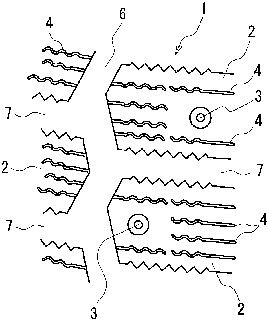
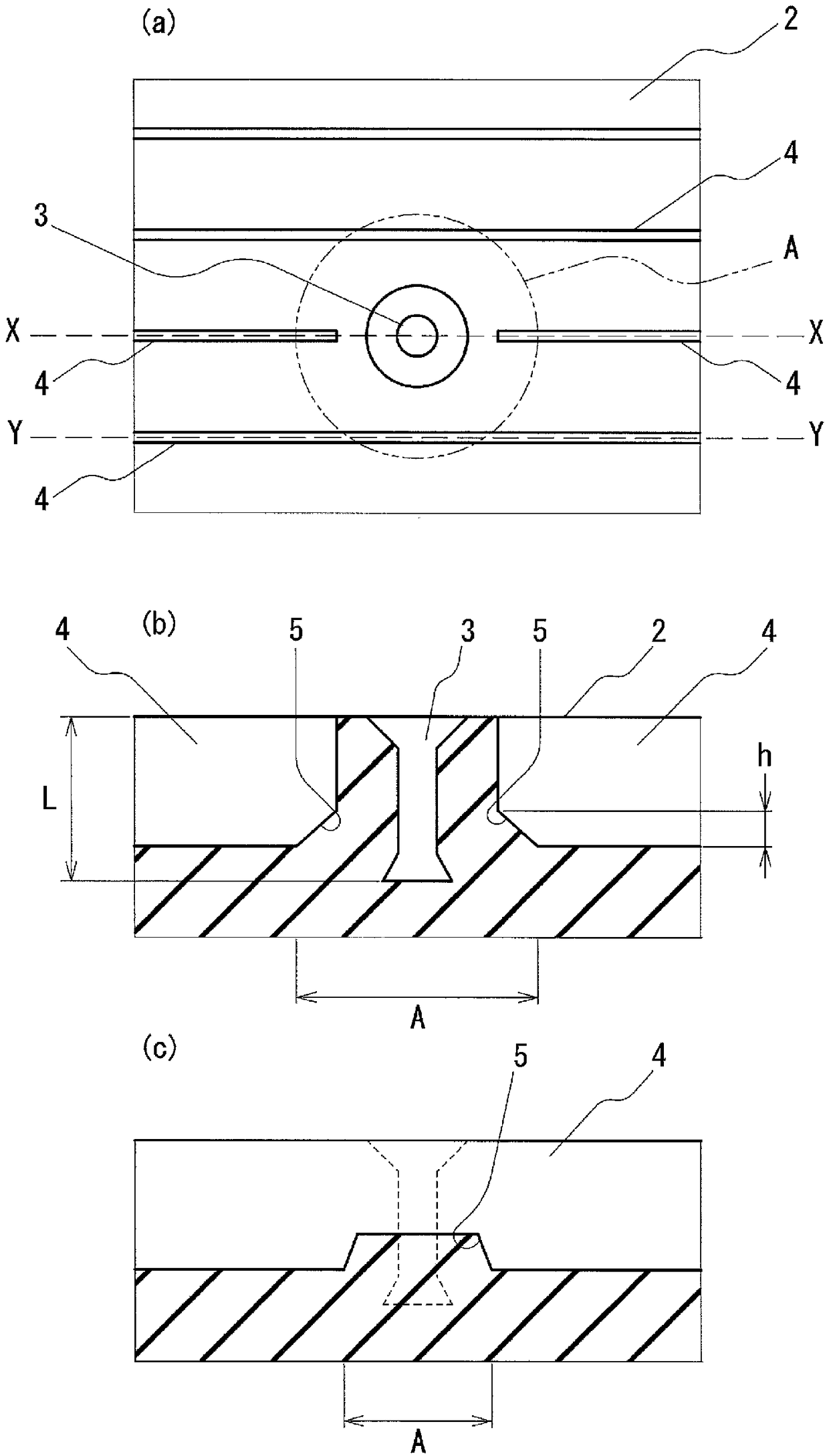
[0040] Seven types of pneumatic tires (tyre The size is 205 / 55R16; conventional examples, examples 1 to 6) were subjected to vulcanization molding. Such as Figure 7 As shown in (a) and (b), in the pneumatic tire of the conventional example, the sipe 4 in the peripheral region of the stud hole 3 does not have a bottom raised portion. The pneumatic tires of Examples 1 to 6 have in common image 3 (a), (b), and (c) shown in the form of the raised bottom portion, but the size of each raised bottom portion is different as described in Table 1. In the table, the "arrangement ratio of raised bottom portion" is the percentage of the total length of the raised sipe in the peripheral area to the total length of the sipe located in the peripheral area, and the "maximum raised height h ” is expressed as a ratio relative to the distance L from the surface of the block to the bottom of the stud hole.

[0041] Studs were driven into the stud holes of the obtained pneumatic tire to manuf...


PUM


Abstract

The present invention provides a pneumatic tire in which the studs are suppressed from coming off when the studs are driven into the stud holes, and the performance on ice and snow is improved above the conventional level. The pneumatic tire has a tread (1) with a plurality of blocks (2) divided by grooves (6) extending in the tire circumferential direction and grooves (7) extending in the tire width direction. There are a plurality of sipe (4) and stud holes (3), characterized in that at least a part of the bottom of the sipe (4) located in the peripheral area A of the stud holes (3) is raised.

Description

technical field [0001] The present invention relates to a pneumatic tire capable of driving studs. Background technique [0002] In severe winter regions such as Northern Europe and Russia, pneumatic anti-skid tires (tires with anti-skid punctures) are mainly used as winter tires. This antiskid tire is constructed by arranging stud holes in a plurality of blocks of the tread, and driving studs into the stud holes. The studs embedded in the tread grip the ice and snow road surface, thereby providing excellent running performance (performance on ice and snow) such as braking performance and drivability. [0003] However, the cleats may fall off due to long-term use or use under severe conditions such as driving on dry roads. Problems arise that when the studs fall off, the performance on ice and snow is reduced, and the fallen studs deteriorate the environment around the road, and the like. [0004] In addition, in order to further improve performance on ice and snow, a plu...

Claims


Application Information

Patent Timeline
Patent Type & Authority Patents(China)
IPC IPC(8): B60C11/16B60C11/12
CPCB60C11/16B60C2011/0346B60C2011/1213B60C11/1263B60C11/11B60C11/1656B60C11/1236B60C11/12B60C11/0306B60C11/1204B60C11/1668
Inventor 远藤广树
Owner THE YOKOHAMA RUBBER CO LTD
Why Eureka
Try Eureka