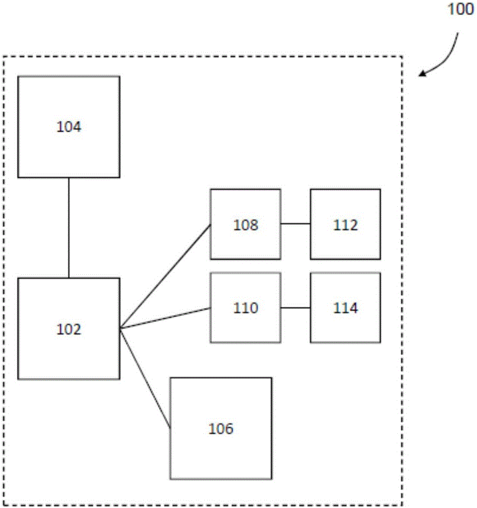
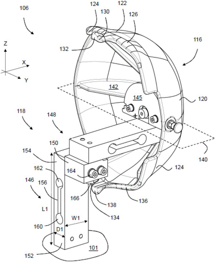
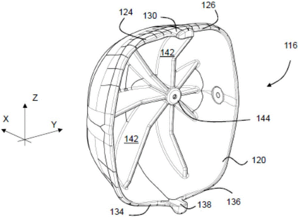
[0047] figure 1 is a schematic diagram of an ophthalmic surgery simulator 100 . The simulator 100 includes a computer 102 having memory and a processor. The processor is arranged to execute software stored in the memory, in particular software for simulating a medical procedure such as an ophthalmic operation. Computer 102 is connected to VDU 104 , stand 106 , first haptic system 108 and second haptic system 110 .
[0048] The VUD is configured with two separate outputs mounted behind respective eyepieces which are closer to the ophthalmic microscope.
[0049] Each haptic system 108, 110 includes first and second handpieces 112, 114, respectively. Haptic systems 108, 110 and handpieces 112, 114 will not be described in detail. Generally, the haptic systems 108, 110 are configured to monitor the position of the handpieces 112, 114, respectively, and provide force feedback. As the user operates the handpieces 112, 114, the computer 102 moves the virtual tool in the virtual environment and can provide feedback to the operator.
[0050] Standoff 106 is shown more specifically at figure 2 middle. In use, for the support 106, principal axes X, Y, Z are defined. The X direction is the vertical axis of the patient's body when standing, ie the positive direction from the feet to the head. The Y direction is lateral and the Z direction is the patient's anterior-posterior axis.
[0051] The mount 106 includes a head model 116 and a sensing structure/mounting structure 118 . Head model 116 is shown in further detail in image 3 and Figure 4, which represents the outer portion of a portion of a human head and includes a hollow concave shell 120 that is generally semi-ellipsoidal. The housing 120 is bisected by a coronal plane 140 defining opposing anterior regions 122 and posterior regions 124 . The sagittal plane 141 that bisects the housing 120 is also shown in Figure 4 middle. At the edge of the front area 122, a right anterior eye pocket edge area 124 and a left anterior eye pocket edge area 126 are respectively defined, between which there is provided a The upper nose protrusion 130 on the top. The outer surface of the housing 120 , especially in the region of the eye and nose parts, represents the outer contour of the upper part of the human face bisected by the sagittal plane. Model 116 includes some external configurations for the various soft tissues covering the cranium.
[0052] With respect to the rear region of the housing 120 , the left rear eye pocket rim region 134 and the right rear eye socket rim region are each provided with an upper nasal protrusion 138 extending therebetween and corresponding to the sagittal plane 141 . Thus, housing 120 is generally symmetrical with respect to coronal plane 140 dividing frontal region 122 and rearward region 124 .
[0053] The reinforcing rib 142 is disposed in the casing 120 to strengthen the casing 120 . A mounting structure 144 in the form of a boss 144 is provided in the middle of the rib 142 . The boss 144 is located on the coronal plane 140 (midway between the anterior region 122 and the posterior region 124), but is offset from the sagittal plane 141, specifically, the boss is aligned between the right anterior eye pocket rim region 126 and the left posterior ocular Between the pocket edge regions 136.
[0054] refer again figure 2 , the installation structure 145 is used to install the boss 144 . For the sensor structure/mounting structure 118 , a first force sensor 146 is provided which is connected to a second force sensor 148 via a joint 150 . The first and second force sensors are connected in series.
[0055] The first force sensor 146 is an elongated cuboid having a first end 152 and a second end 154 . The force sensor 146 has a depth D1, a width W1 and a length L1. The width L1 is greater than the depth D1, and the length L1 is greater than the width W1. The open slot 156 extends across the width W1 of the first force sensor 146 . The open slot 156 extends along a portion of the length L1 of the force sensor 146 . The open slot 156 has a generally rectangular cross-section 158 and terminates in two circular cross-sections at either end. This is to eliminate stress concentrations in the force sensor.
[0056] The second force sensor 148 is substantially identical to the first force sensor 146 (although in use is positioned at a different angle) and thus will not be described in detail.
[0057] Strain gauges (not shown) are provided on the surfaces of the force sensors 146 and 148 to measure elastic deformation of the force sensors under load. Note that the area of the first force sensor located in the area of the slot 156 becomes smaller in the XY plane. Accordingly, the second moment of area of the first sensor 146 with respect to the X-axis is smaller than the moment of area with respect to the other two axes. Accordingly, the force sensor 146 undergoes a relatively large elastic deformation in the X-axis, which is detected by the strain gauges and indicates the magnitude of the force applied to the sensor, especially the force sensor 146 in the Y-axis direction. The force on the second end 154 (ie, the bending moment in the X direction). Once calibrated, the strain gauge readings can be converted to force applied on the tip of the sensor.
[0058] Similarly, the second force sensor 148 has a relatively small second moment of area with respect to the Y axis, therefore, a force in the Z direction will cause a relatively large amount of elastic bending on the Y axis of the second force sensor 148, which The amount of elastic bending can be detected by a strain gauge.
[0059] The joint 150 includes a first attachment structure 164 and a second attachment structure 166 at 90 degrees relative to the first attachment structure.
[0060] In use, the mount 106 is assembled in the following manner.
[0061] The first end 152 of the first force sensor 146 is mounted on the base 101 . like figure 2 As shown, the first force sensor 146 extends in the main axis Z direction. The junction 150 is disposed on the second end 154 of the first force sensor 146 . The first attachment structure 164 is attached to the second end 154 of the first force sensor 146 . The second force sensor 148 is attached to the junction 150 by a second attachment structure 166 . The second force sensor 148 is perpendicular to the first force sensor and extends in the X direction. It should be noted that the first force sensor 146 and the second force sensor 148 are not in direct contact, but are joined by a single force path through the junction 150 .
[0062] A second force sensor 148 is connected to the mounting structure 145 of the head model 116 to which the boss 144 is attached. Therefore, the face of the model 116 , especially the front region 122 faces the +Z direction. Thus, the rear region and the face it defines face in the -Z direction.
[0063] Accordingly, first force sensor 146 and second force sensor 148 are capable of detecting forces applied to model 116 in the Y and Z directions, respectively.
[0064] In use, such as figure 2 As shown, the doctor places the head model 116 with the +Z direction facing the -Z direction. During the procedure, the physician will grasp the handpieces 112, 114 and manipulate the handpieces 112, 114 in the space where the patient's left eye would normally be (ie, the area adjacent the left front eye pocket rim area 126).
[0065] Note that the working volume of the handpieces 112 , 114 is located in the area of the second anterior eye pocket rim area 126 .
[0066] A physician can place his or her arms and hands on the outer surface of housing 120, especially figure 2 on the front area of the structure shown.
[0067] When the doctor applies excessive force in the -Z direction to the head model 116 , the second force sensor 148 will detect the force, and the force will be fed back to the computer 102 . The computer will then perform two actions, first it will defocus the picture on the VDU 104 to simulate the patient moving out of focus (as would happen in reality). Second, the eyes will move in the X direction, since in practice the force will cause the head to tilt back relative to the neck.
[0068] Similarly, when excessive force in the +Y or -Y direction is sensed by the first force sensor 146, the computer 102 moves the virtual eye on the VDU 104 to reflect the virtual result of the excessive force applied.
[0069] Simulator 100 also provides virtual (via VDU) and/or audio instructions on how to correct the problem. In the event that excessive force is applied in the -Z direction, the computer 102 instructs the user to relax his or her hand, which will refocus and reposition the image on the VDU. In the case of excessive force in the +Y or -Y direction, the user will be instructed to push the head back towards the original position to restore the image.
[0070] When the user wishes to operate on the right eye, the phantom 116 can be rotated 180 degrees about the X-axis so that the rear region 124 faces the user. Because the boss 144 is offset from the sagittal plane 141, the working volume of the handpieces 112, 114 will be within the area of the right posterior eye pocket rim region 166 once the rotation is complete.
[0071] Various modifications will fall within the scope of the present invention. Instead of two force sensors, a single force sensor or three force sensors may also be provided to detect the force applied by the operator in each of the X, Y and Z directions. In the above example, for ophthalmic surgery, the forces in the Z and Y directions are the most important and most commonly encountered forces in such surgery.
[0072] Any other type of force sensor or displacement sensor can be used in the present invention. Values such as force or displacement in rotation sensing can be detected.
[0073] It's conceivable that a similar kind of system could be used for any other type of surgery, especially one in which the doctor places part of his body on the patient. For example, any type of facial surgery or dental surgery would benefit from the present invention.
[0074] The head model 116 can be made more flexible, for example, a layer of softer material can be added on the hard shell 120 to simulate muscle cartilage and/or skin. In addition, hair can be arranged on the model to provide more flexibility for the operator. realistic environment.