Electrical switching device with parallel switching paths

A technology for switchgear and electric switches, applied in electric switches, electronic switches, high-voltage/high-current switches, etc., can solve problems such as eliminating failures, and achieve the effect of reducing manufacturing costs

Active Publication Date: 2019-09-27
SIEMENS AG
View PDF2 Cites 0 Cited by
  • Summary
  • Abstract
  • Description
  • Claims
  • Application Information

AI Technical Summary

Problems solved by technology

[0003] But if the parallel switching paths are disconnected shortly before the current zero crossing, especially before the large half-wave, then due to the elimination of the attempt causes additional current to flow in the switch path
If the switching path does not have the required cancellation capability to break the current in subsequent current zero crossings, resulting in cancellation failure

Method used


Image

  • Electrical switching device with parallel switching paths
  • Electrical switching device with parallel switching paths
  • Electrical switching device with parallel switching paths

Examples


Embodiment Construction

[0020] All figures are only schematic and show the invention in its main components. Here, the same reference numbers correspond to elements with the same or similar function.

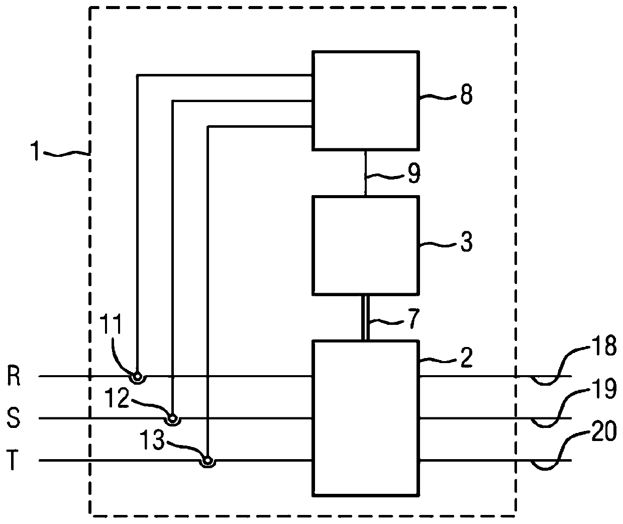
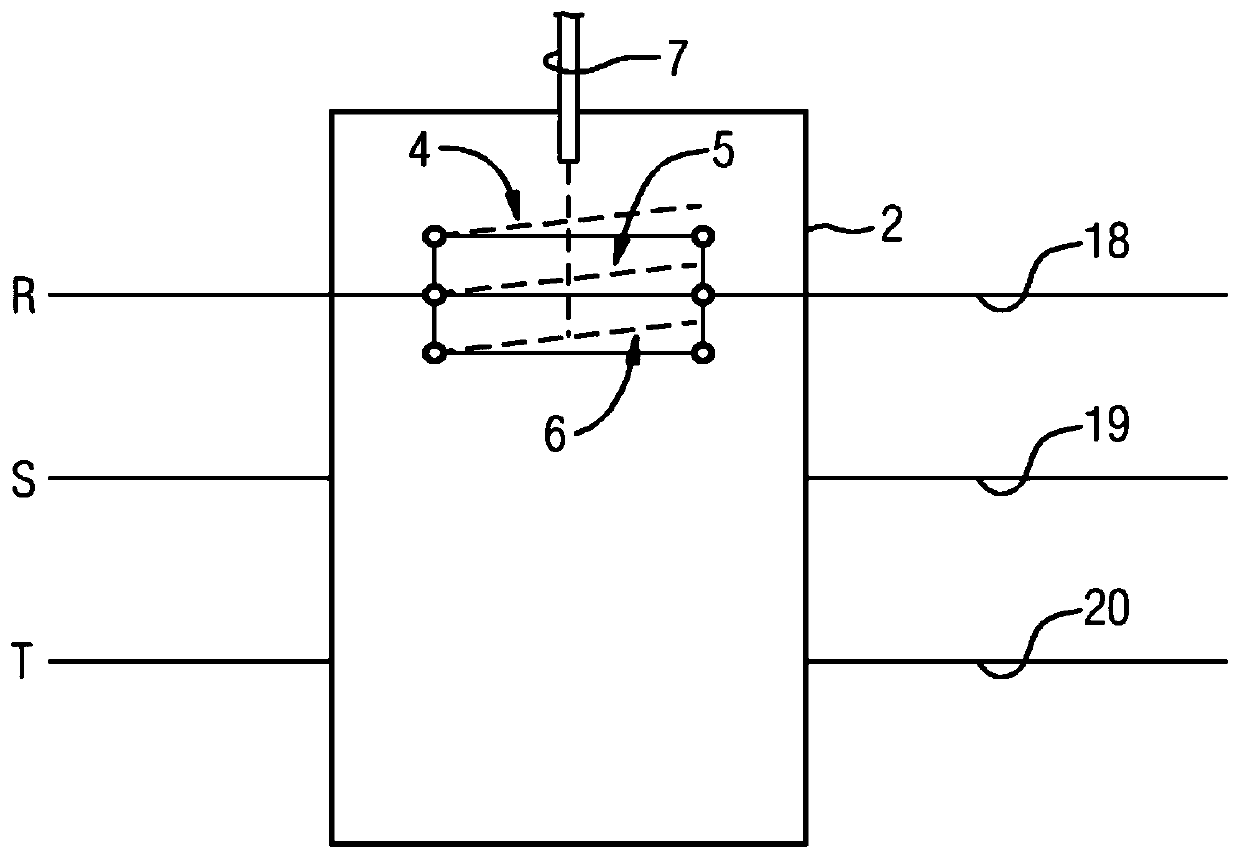
[0021] A three-phase electrical switchgear 1 for medium or high voltage is shown, eg a generator switch. Consider, for example, the case of a short circuit. The switching device 1 is designed to switch on or off a temporally phase-shifted current. For this purpose there is a contact system 2 which can be switched off for each of the three phases 18 , 19 , 20 (R, S, T) of the power line. In this case, at least one of the phases 18 , 19 , 20 , preferably all phases 18 , 19 , 20 , are assigned three parallel interruption units. The interruption unit is, for example, a vacuum tube. It has the property that its switching paths 4 , 5 , 6 recover their dielectric strength very quickly when switched off.

[0022] The drive device 3 of the switchgear 1 is designed for simultaneously driving all contact sys...


PUM


Abstract

The invention relates to a method for operating an electrical switching device (1). Furthermore, the invention relates to such an electrical switching device (1). In order to ensure reliable operation of the electrical switching device (1) with parallel switching paths (4, 5, 6) for the phases (18, 19, 20), which have a smaller switching power capability, it is recommended that the current zero crossings (31, 32) in the phase (18, 19, 20) be collected and at least one switching mechanism (3) operatively connected to the switching path (4, 5, 6) The control is such that all parallel switching paths (4, 5, 6) assigned to this phase (18, 19, 20) are disconnected within a time window (21, 22, 23, 24) which is the same as that in this phase The current zero crossings (31, 32) in (18, 19, 20) are related.

Description

technical field [0001] The invention relates to a method for operating an electrical switching device. Furthermore, the invention relates to such an electrical switching device. Background technique [0002] Electrical switching devices are known from the prior art in which at least two parallel switching paths are associated with a phase. In the case of electrical switchgear, the conduction of high rated currents requires low-ohmic switching paths in order to meet temperature requirements and in particular to limit heating of switchgear components. The use of parallel switching paths makes it possible to reduce the overall resistance of the switching path arrangement. [0003] But if the parallel switch paths are disconnected shortly before the current zero crossing, especially before the large half-wave, then due to the elimination of the attempt resulting in additional current flowing in the switch path. If the switching path does not have the required cancellation c...

Claims


Application Information

Patent Timeline
Patent Type & Authority Patents(China)
IPC IPC(8): H01H9/56
CPCH01H9/563H01H33/66H03K5/153H03K17/13H01H9/40H01H9/56
Inventor K.弗罗因特H.卡勒塔A.马利茨U.舒曼恩E.D.泰勒
Owner SIEMENS AG
Why Eureka
Try Eureka