
Electric stirring cup capable of being operated manually

A technology of electric stirring and electric motor, which is applied in the direction of mixer accessories, mixers with rotating stirring devices, dissolving, etc. It can solve the problems of blocking, destructive samples, low efficiency, time-consuming and laborious, etc., and achieves convenient use and good stirring effect , Improve the mixing effect

Inactive Publication Date: 2017-04-26
HEFEI ZHIHUI LONGTUTENG INTPROP CO LTD
View PDF0 Cites 11 Cited by
  • Summary
  • Abstract
  • Description
  • Claims
  • Application Information

AI Technical Summary

Problems solved by technology

[0002] In many fields, it is necessary to carry out chemical testing on the finished and semi-finished products. At present, a small number of samples are generally selected for testing in chemical testing. During testing, stirring and mixing between samples or between samples and testing reagents is often required. There are two main types of chemical testing and mixing at present. One method is to use a beaker and other containers to manually stir the stirring rod for mixing, which is inefficient, time-consuming and laborious, but it can be implemented in any environment; the other is to use an electric stirring cup for mixing, which has high efficiency and good effect, but Stirring will not be possible in places without power supply such as outdoors or power outages, and even if you want to use a stirring rod to stir because of the blocking of the stirring blades, you will be greatly hindered; Realize the mixing between sample reagents, which is very destructive to the sample, and requires a new stirring method that can still ensure the stirring effect at a lower speed.

Method used


Image

  • Electric stirring cup capable of being operated manually
  • Electric stirring cup capable of being operated manually

Examples


Embodiment Construction

[0015] The technical solution of this patent will be further described in detail below in conjunction with specific embodiments.

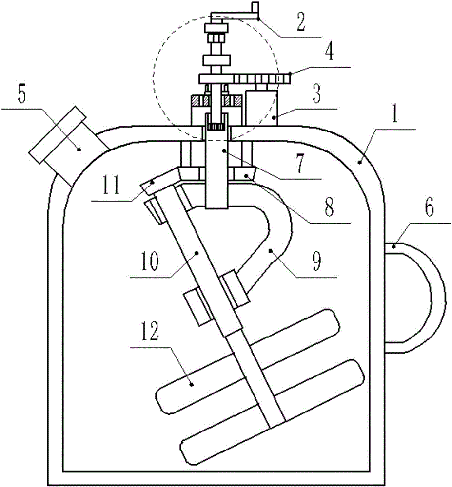
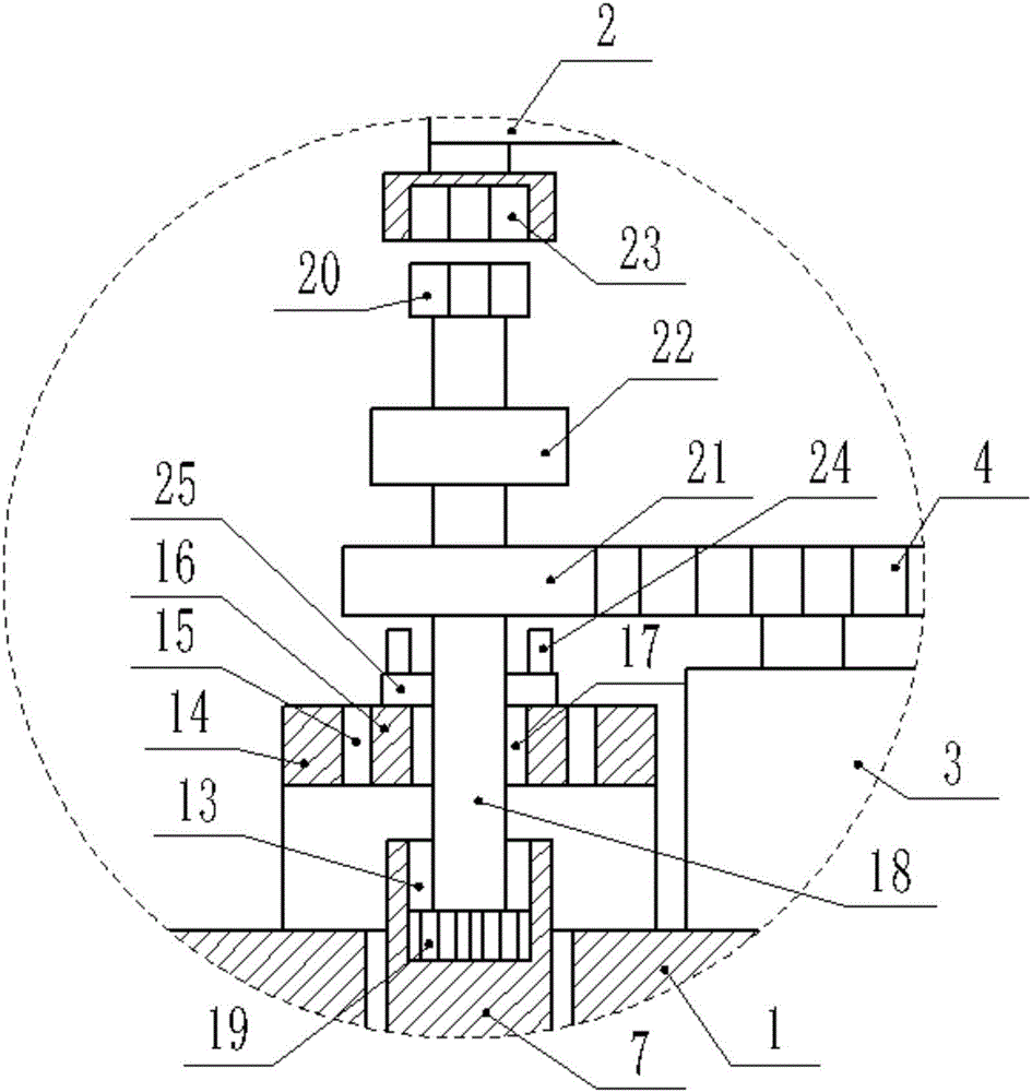
[0016] see Figure 1-2 , a manual electric stirring cup, including a cup body 1, a hand wheel 2 and an electric motor 3, the electric motor 3 is fixedly connected to the upper end of the cup body 1, and the output shaft of the electric motor 3 is fixedly connected to a driving gear 4 The upper end of the cup body 1 is fixedly connected with a feed port 5, the side wall of the cup body 1 is also fixedly connected with a handle 6, the center of the top plate of the cup body 1 is connected with a transmission shaft 7 in rotation, and the lower end of the top plate of the cup body 1 is fixedly connected with an umbrella Gear Ⅰ8, the drive shaft 7 passes through the inner hole of the bevel gear Ⅰ8 and leads to the bottom of the bevel gear Ⅰ8, the lower end of the drive shaft 7 is fixedly connected with a 'V'-shaped transfer shaft 9, and the two shaft ar...


PUM


Abstract

The invention discloses an electric stirring cup capable of being operated manually. The electric stirring cup comprises a cup body, a hand wheel and an electric motor, wherein a top plate of the cup body is rotationally connected with a transmission shaft, the lower end of the top plate of the cup body is fixedly connected with a bevel gear I, the lower end of the transmission shaft is fixedly connected with a coupling shaft, a stirring shaft is rotationally connected to the coupling shaft, the upper end of the stirring shaft is fixedly connected with a bevel gear II, and the lower part of the stirring shaft is fixedly connected with a stirring blade; and the upper end of the transmission shaft is provided with a gear groove, the upper end of the top plate of the cup body is fixedly connected with a support plate, a middle rotating shaft is rotationally connected with the center of the support plate through a rolling bearing, a driving shaft is in slip connection with the center of the middle rotating shaft through a linear bearing, the lower end of the driving shaft is fixedly connected with a driving gear, the upper end of the driving shaft is fixedly connected with a fixture block, and a transmission gear is fixedly connected to the driving shaft. The electric stirring cup disclosed by the invention is good in rotation effect and small in damage to a sample, can be switched between manual operation and electric operation conveniently, is convenient and flexible in use, and is labor-saving and efficient.

Description

technical field [0001] The invention relates to a stirring device, in particular to a manual electric stirring cup. Background technique [0002] In many fields, it is necessary to carry out chemical testing on the finished and semi-finished products. At present, a small number of samples are generally selected for testing in chemical testing. During testing, stirring and mixing between samples or between samples and testing reagents is often required. There are two main types of chemical testing and mixing at present. One method is to use a beaker and other containers to manually stir the stirring rod for mixing, which is inefficient, time-consuming and laborious, but it can be implemented in any environment; the other is to use an electric stirring cup for mixing, which has high efficiency and good effect, but Stirring will not be possible in places without power supply such as outdoors or power outages, and even if you want to use a stirring rod to stir because of the blo...

Claims


Application Information

Patent Timeline
IPC IPC(8): B01F7/30B01F15/00
CPCB01F27/212B01F27/213B01F27/951B01F35/322B01F35/30
Inventor 不公告发明人
Owner HEFEI ZHIHUI LONGTUTENG INTPROP CO LTD
Learn More