Photothermal waveguide-based microfluidic chip and its microfluidic method

A microfluidic chip and microfluidic technology, applied in the field of optofluidics, can solve problems such as functional limitations of optically controlled microfluidics, single fluid flow form, scattering of optical components, etc., and achieve fast, convenient and low-cost manufacturing methods , Stable effect of stimulating heat

Active Publication Date: 2018-12-07
SOUTH CHINA NORMAL UNIVERSITY
View PDF4 Cites 0 Cited by
  • Summary
  • Abstract
  • Description
  • Claims
  • Application Information

AI Technical Summary

Problems solved by technology

In view of the limitations of the current traditional laser beam, the current light-controlled microfluidic technology has several major deficiencies: 1. The excitation equipment is complex and the loss is large
Starting from the light source, the laser needs to go through a complex optical path and then interact with the material. Optical components will scatter and absorb part of the energy, resulting in waste
2. The form of fluid flow generated by the direct laser excitation method is single, and generally only stimulates the vertical flow of the fluid, which ultimately causes the function of the light-controlled microflow technology to be limited to fluid heat transfer and mass transfer.

Method used


Image

  • Photothermal waveguide-based microfluidic chip and its microfluidic method
  • Photothermal waveguide-based microfluidic chip and its microfluidic method
  • Photothermal waveguide-based microfluidic chip and its microfluidic method

Examples


Embodiment 1

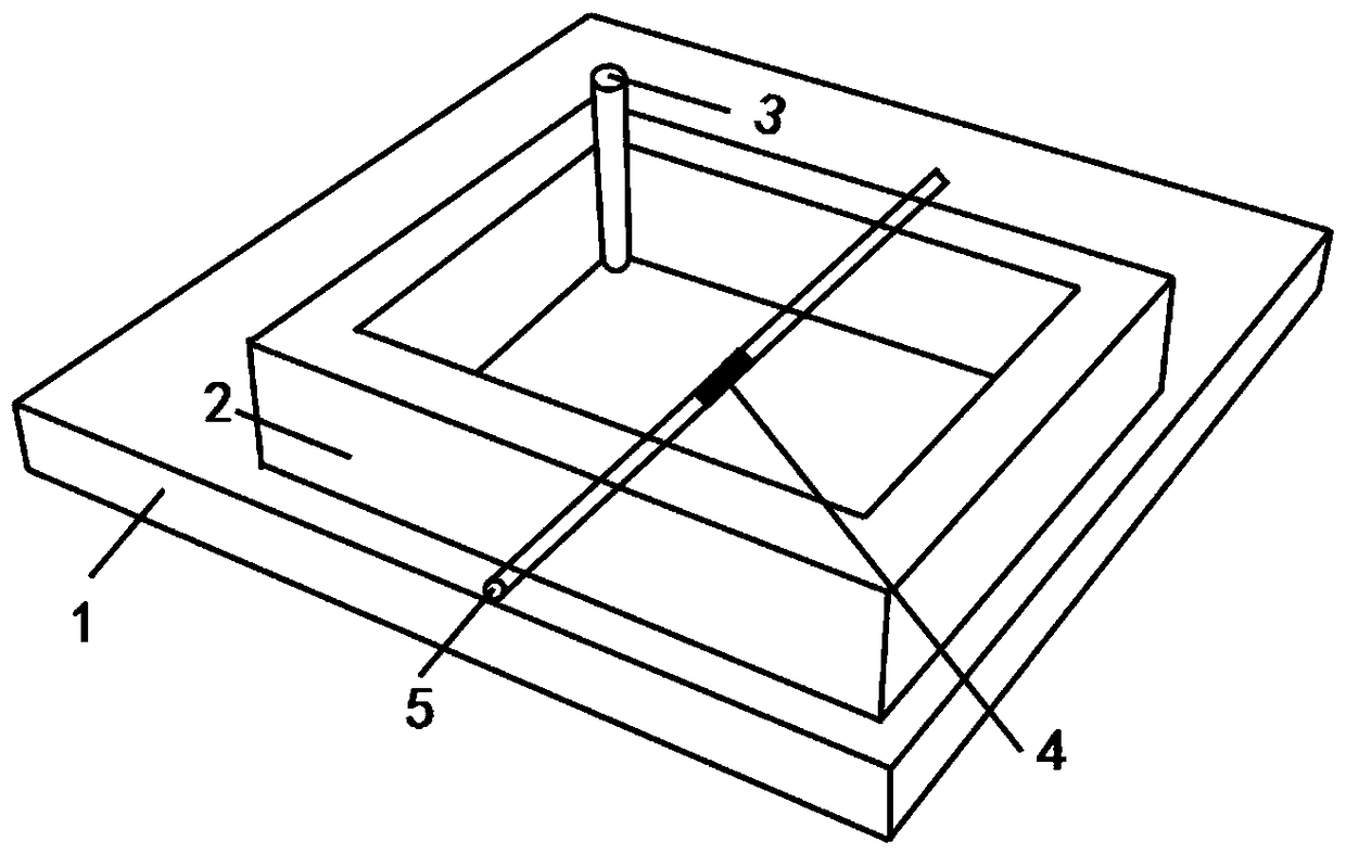
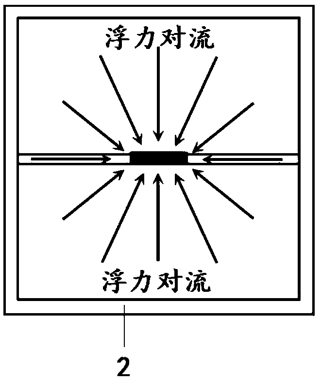
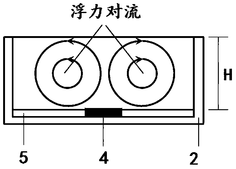
[0044] This embodiment primarily produces a vertical vortex flow dominated by buoyant convection. In this embodiment, the microfluidic pump injects more liquid to form a thicker fluid layer, and the thickness of H is 30-100 μm. At this time, the heat that excites the photothermal waveguide in the microfluid diffuses in the microfluid, and the microfluid close to the heat source Density decreases due to local expansion due to increased temperature. This redistribution of density within the microfluidics creates the buoyancy driving force. The direction of the driving force is vertical, so the driving fluid flows from the low position to the high position, and then from the high position to the low position, so that the vertical vortex is formed in such a cycle. The vertical direction of its convection is as Figure 2b shown. At the same time, since the direction of thermal diffusion is axisymmetric to the photothermal waveguide, the horizontal direction of the generated conv...

Embodiment 2

[0046] This embodiment primarily produces a horizontal vortex flow dominated by thermocapillary convection. In this embodiment, the microfluidic pump injects less liquid to form a thinner fluid layer, the thickness of H is 5-20 μm. At this time, the heat that excites the photothermal waveguide in the microfluid diffuses in the microfluid, and on the surface of the microfluid, The surface tension of the microfluidics near the center becomes smaller as the temperature increases. This redistribution of microfluidic surface tension creates shear stress. Since this phenomenon only occurs on the microfluidic surface, the direction of the driving force is horizontal, so the driving fluid flows from the low surface tension region (high temperature region) to the high surface tension region (low temperature region), and thus forms a horizontal vortex. Its convective direction is as Figure 3a shown. Since the direction of thermal diffusion is axisymmetric to the microfluidic surface...

Embodiment 3

[0048] In this embodiment, horizontal and vertical mixed vortex flows are mainly generated. The micro-flow pump injects an appropriate amount of liquid so that the thickness H of the micro-fluid is 20-30 μm. At this time, the redistribution of the density inside the microfluid and the surface tension on the surface of the microfluid is caused by exciting the photothermal waveguide in the microfluid. The former forms buoyant convection, the latter forms thermocapillary convection, and the two types of convection overlap each other.

[0049] Embodiments of the present invention and experimental operations are described in further detail below in conjunction with examples and drawings, but the embodiments of the present invention are not limited thereto.

[0050] A single-mode silica fiber (SMF-28, Corning Company, USA) was drawn by flame heating stretching method, and a micro-nano waveguide with a diameter of 1.0 μm and a length of 2 mm was drawn. The photothermal waveguide is...


PUM


Abstract

The invention discloses a micro-fluidic chip based on a photothermal waveguide and a micro-fluidic method of the micro-fluidic chip. The chip comprises the photothermal waveguide, a microflow chamber, an optical signal input port, a microflow pump and microfluid, wherein the photothermal waveguide is formed by assembling a photothermal conversion material with a micro-nano waveguide, the photothermal waveguide is submerged at the bottom of the microflow chamber, and an optical signal sent by a light source is transmitted on the photothermal waveguide; and the microflow pump is connected with the microflow chamber by virtue of a pipeline. The photothermal waveguide generates heat under the excitation of the optical signal, then generates a temperature gradient in the whole microfluid, and inductively generates buoyancy convection taking vertical type vortex flow as a characteristic and thermo-capillary convection taking horizontal type vortex flow as a characteristic. By virtue of the microflow pump, the thickness of a fluid layer can be changed so as to control a flow mode of the microfluid. By virtue of the power of the optical signal, the heat of the photothermal waveguide can be changed so as to control the flow intensity of the microfluid. The method disclosed by the invention is quick and convenient, is low in cost, is efficient, and can generate multiple forms of vortex flows.

Description

technical field [0001] The invention belongs to the field of optofluidic technology, and in particular relates to a microfluidic chip based on a photothermal waveguide and a microfluidic method thereof. Background technique [0002] In the microfluidic chip, the generation and control of microfluidic flow is one of the basic operations to realize the sample preparation, reaction, separation, detection and other modules of the biochemical analysis process. Early microfluidic flow technologies were mainly realized through micropump valve devices and complex fluid channels. In the middle and late 21st century, with the development of devices towards integration and miniaturization, the vigorous development of microfluidic chip technology and the organic combination of optical technology, the two complement each other, created the birth of a new technology field, that is, optically controlled microfluidic technology . The method of using photothermal materials to convert light...

Claims


Application Information

Patent Timeline
Patent Type & Authority Patents(China)
IPC IPC(8): B01L3/00
CPCB01L3/5027B01L2300/12
Inventor 邢晓波郑嘉鹏周瑞雪张俊优何赛灵杨剑鑫史可樟
Owner SOUTH CHINA NORMAL UNIVERSITY
Why Eureka
Try Eureka