
Processing and positioning method and positioning fixture for the end face of the intake flange of combined exhaust manifold

A technology for exhaust manifolds and intake flanges, which is applied in the field of processing and positioning methods for the end faces of intake flanges of combined exhaust manifolds and positioning fixtures. The problems of smoothness and distance deviation, etc., achieve the effect of simple and fast operation, reduce labor intensity and ensure the quality of assembly

Active Publication Date: 2018-09-18
FEILONG AUTO COMPONENTS CO LTD
View PDF5 Cites 0 Cited by
  • Summary
  • Abstract
  • Description
  • Claims
  • Application Information

AI Technical Summary

Problems solved by technology

However, due to the inevitable errors in the casting process of exhaust manifold blanks, coupled with factors such as cooling deformation of the casting slab, the distance between the outer circle of the air passage opening and the center of the air passage varies, so the positioning of the outer surface support often brings the center of the air passage. The size of the end face of the inlet flange is different
In this way, when the exhaust manifold is assembled with the engine block, it will inevitably cause the deviation of the air passage center of the two exhaust manifolds, which will affect the smooth exhaust of the exhaust manifold, and then affect the overall quality of the engine and the quality of the engine. Performance, which is also an important factor that has troubled exhaust manifold manufacturers for a long time

Method used


Image

  • Processing and positioning method and positioning fixture for the end face of the intake flange of combined exhaust manifold
  • Processing and positioning method and positioning fixture for the end face of the intake flange of combined exhaust manifold
  • Processing and positioning method and positioning fixture for the end face of the intake flange of combined exhaust manifold

Examples


Embodiment 1

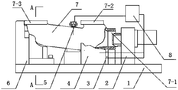
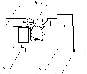
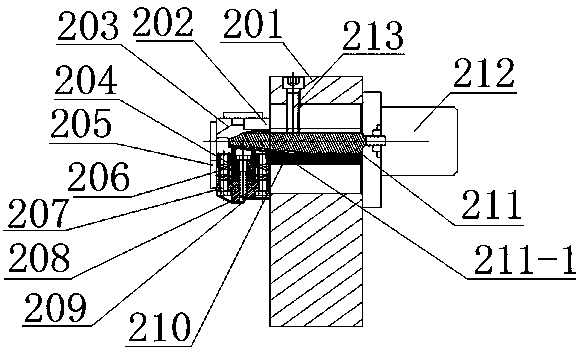
[0027] Such as figure 1 , 2 , 3, 4, 5, 6, and 7, the combined exhaust manifold of the present invention is formed by connecting two exhaust manifolds 7 to each other through the combined connection hole 7-1, in order to realize After docking, the intake flanges 7-2, 7-3 of the two-stage exhaust manifold 7 are smoothly connected with the engine block, and the smooth exhaust of the engine is ensured. The end face of the intake flange of the combined exhaust manifold of the present invention In the processing and positioning method, the combined connection holes 7-1 of the two-stage exhaust manifold 7 are processed respectively based on the end faces of the billet intake flanges 7-2 and 7-3, and then each intake method is processed. The connecting end face of Lan 7-2, 7-3. The positioning method includes reference positioning and auxiliary support positioning, and the reference positioning takes the combined connection hole 7-1 as a positioning reference. The auxiliary support...

Embodiment 2

[0037] see figure 1 , figure 2 , image 3 , Figure 4 , Figure 5 , Image 6 As a further improvement to the technical solution of Embodiment 1, the side support positioning fixture 4 and the side pressing mechanism 3 can be set in 2 or 3 sets, such as processing the exhaust manifold of a four-cylinder engine can be set in 2 sets of side parts Support positioning jig 4 and side pressing mechanism 3, such as processing the exhaust manifold of a six-cylinder engine, 2 or 3 sets of side supporting positioning jig 4 and side pressing mechanism 3, that is, each intake flange A group of side support positioning fixtures 4 and side pressing mechanism 3 are provided, the clamping is firmer and the processing is smoother. Secondly, the first, two, three, four, five, six, seven, eight, nine driving mechanisms 212, 410, 414, 408, 602, 605, 307, 304, 503 can adopt corner hydraulic cylinders, making the connection structure more Simple, motion adjustment control is more convenient a...


PUM


Abstract

The invention discloses a machining and locating method for a combined type exhaust manifold air inflow flange end face. The method comprises the steps of reference location and auxiliary supporting location. In reference location, a combined connecting hole serves as a locating reference. The auxiliary supporting location comprises Y-axial supporting location and Z-axial supporting location; in Y-axial supporting location, the side portion of an air inflow flange serves as a locating reference; and in Z-axial supporting location, the end face of the bottom side of the air inflow flange serves as a locating reference. Locating clamps used for the machining method comprise the clamp, the combined connecting hole locating clamp, the side portion supporting locating clamp and the tail end supporting locating clamp. According to the machining and locating method and the locating clamps for the combined type exhaust manifold air inflow flange end face, the physical size of the air inflow flange and relative machining precision of all air inflow flanges can be effectively guaranteed, so that after two sections of an exhaust manifold are connected in a combined mode, the end faces of all air inflow flanges can be tightly attached to the connecting end face of an engine cylinder, and further the whole assembly quality of an engine exhaust system is guaranteed.

Description

technical field [0001] The invention belongs to the technical field of engine exhaust manifold processing, and in particular relates to a method for processing and positioning an intake flange end face of a combined exhaust manifold and a positioning fixture. Background technique [0002] In order to facilitate the final assembly, the engine exhaust manifold generally adopts a combined structure, that is, it is composed of segments through the butt joint of the air passage. This kind of exhaust manifold production process is also usually after the finished products are processed in sections, and then combined and installed when assembled with the engine block. Therefore, it is necessary to make the relative position of each section of the air passage consistent with the end face of the intake flange, so as to ensure the smooth exhaust of the engine. At present, most of the processing of the end face of the intake flange of the exhaust manifold adopts the lower support at bo...

Claims


Application Information

Patent Timeline
Patent Type & Authority Patents(China)
IPC IPC(8): B23Q3/08B23Q3/18
CPCB23Q3/082B23Q3/18
Inventor 孙耀忠冯长虹李振河江慧丽赵卫东马朝锋杨海龙孙晶陈旭叶菁谢迎侠袁凯代孟
Owner FEILONG AUTO COMPONENTS CO LTD
Learn More