Portable stage

A portable, stage technology, applied in theaters, buildings, building structures, etc., can solve the problems of inconvenient transportation, occupy a large space, fixed volume, etc., to save transportation space and transportation costs, reduce volume, and reduce distance. Effect

Active Publication Date: 2017-04-26
ZHEJIANG DAFENG IND
View PDF6 Cites 2 Cited by
  • Summary
  • Abstract
  • Description
  • Claims
  • Application Information

AI Technical Summary

Problems solved by technology

This kind of stage steel frame structure cannot be disassembled, the volume is fixed, and it takes up a lot of space during transportation. It requires a large space of transportation for transportation, and it is inconvenient to carry and transport.

Method used


Image

  • Portable stage
  • Portable stage
  • Portable stage

Examples


Embodiment 1

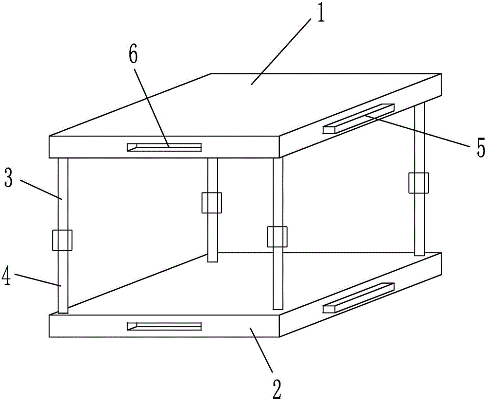
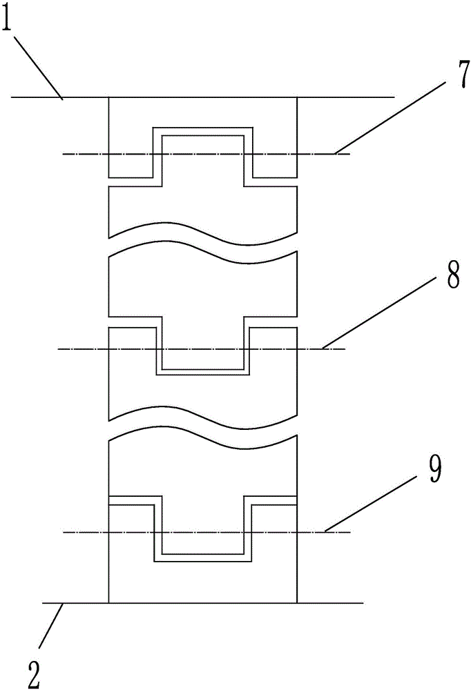
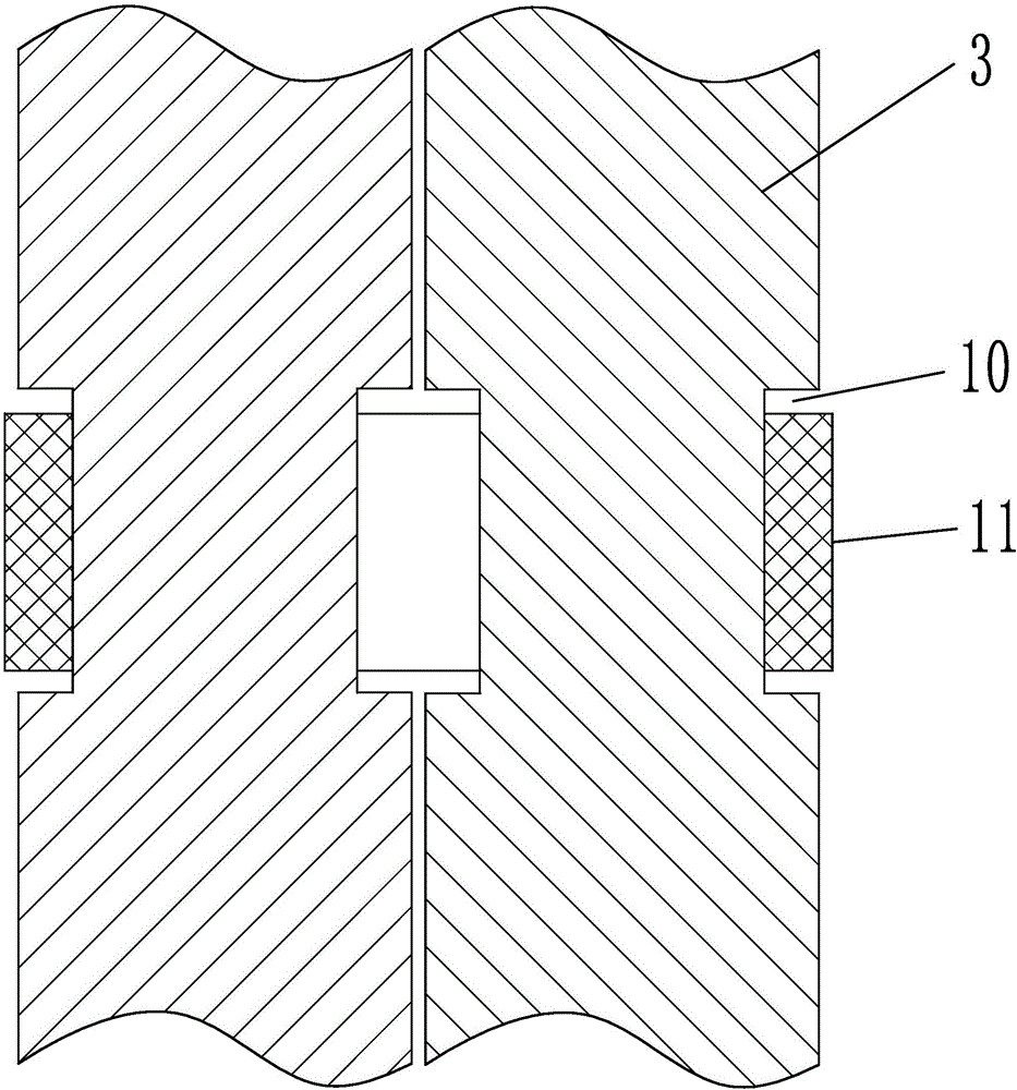
[0023] Embodiment 1: as figure 1 , 2 As shown in , 5, a portable stage includes a stage body, the stage body includes several stage base blocks spliced ​​with each other, the stage base block includes an upper base plate 1 and a lower base plate 2, the opposite sides of the upper base plate are parallel to each other, and the One of the sides or two adjacent sides is provided with a limit protrusion 5, and the other three sides or two adjacent sides are provided with a limit protrusion to cooperate with another upper substrate of the same structure. The limit groove 6 of the upper base plate and the lower base plate have the same structure, and the corners of the upper base plate are provided with connecting arms, and the upper base plate is connected with the lower base plate through the connecting arms; the connecting arms include an upper support arm 3 and a lower support arm 4 , the upper support arm and the lower support arm are hinged through the first hinge mechanism 7...

Embodiment 2

[0025] Embodiment 2: The structure of this embodiment is basically the same as that of Embodiment 1, the difference is that, as Figure 8 As shown, the connecting plate comprises a left connecting plate 27 and a right connecting plate 28, several upper latches 29 are arranged on the left connecting plate, several lower latches 30 are arranged on the right connecting plate, the left connecting plate and the right connecting plate pass through The matching snap connection of the upper latch and the lower latch. One end of the hoop plate is the left connecting plate, and the other end is the right connecting plate, and the left and right connecting plates are just a relative concept of one left and one right. There are several upper teeth on the left connecting plate, and several lower teeth on the right connecting plate. When the hoop plate surrounds the connecting arm, match the upper and lower teeth on the left connecting plate and the right connecting plate. Insertion, mutua...

Embodiment 3

[0026] Embodiment 3: The structure of this embodiment is basically the same as that of Embodiment 1 or 2, the difference is that, as Figure 9 As shown, the two adjacent sides of the upper substrate are provided with outwardly protruding curved protrusions, and the other two adjacent sides are provided with outer edges of the curved protrusions of the upper substrate with the same structure. The limiting recess; the limiting protrusion is located in the middle of the height direction of the outer edge of the convex portion of the curved surface, and the limiting groove is located in the middle of the height direction of the limiting recess. The curved surface convex portion 31 on the upper substrate cooperates with the limiting concave portion 32 of the adjacent upper substrate, the limiting concave portion can limit the curved surface convex portion, the friction between the limiting concave portion and the curved surface convex portion is along the tangential direction, Sinc...


PUM


Abstract

The invention relates to performance equipment, in particular to a portable stage. The portable stage comprises a stage body. The stage body comprises a plurality of mutually-jointed stage base blocks. Each stage base block comprises an upper base plate and a lower base plate. Connecting arms are arranged at the corners of each upper base plate. Each upper base plate is connected with each lower base plate through the corresponding connecting arms. Each connecting arm comprises an upper supporting arm and a lower supporting arm, wherein the upper supporting arm is hinged to the lower supporting arm through a first hinging mechanism, one end, far away from the lower supporting arm, of the upper supporting arm is hinged to the upper base plate through a second hinging mechanism, one end, far away from the upper supporting arm, of the lower supporting arm is hinged to the lower base plate through a third hinging mechanism, and the structures of the first hinging mechanism, the second hinging mechanism and the third hinging mechanism are same. The four adjacent upper supporting arms and the four adjacent lower supporting arms of any four adjacent stage base blocks are connected through hold hoops. The portable stage has the beneficial effects that the size of the portable stage can be changed, occupied space is saved, and the transportation cost of transportation is saved.

Description

technical field [0001] The invention relates to performance equipment, in particular to a portable stage. Background technique [0002] In today's society, product promotion and community activities usually use the form of performances. Before the performance, a stage needs to be built in a preset venue. The existing stage usually adopts a steel frame structure, using a steel plate as the stage table, and using a bracket to support the lower end of the steel plate. stage. This type of stage steel frame structure cannot be disassembled, and its volume is fixed. It takes up a lot of space during transportation, and requires a large space of transportation for transportation, which is inconvenient to carry and transport. Contents of the invention [0003] The present invention mainly aims at the above problems, and provides a portable stage capable of changing its own volume, saving occupied space, and saving transportation costs of transportation means. [0004] The purpos...

Claims


Application Information

Patent Timeline
Patent Type & Authority Applications(China)
IPC IPC(8): E04H3/28E04B1/343E04B1/344
CPCE04B1/34331E04B1/3441E04H3/28
Inventor 丰其云谢海歧姚亮刘榛吴立锋张航
Owner ZHEJIANG DAFENG IND
Why Eureka
Try Eureka