Loading device used for space fabricated type semi-rigid joint test

A loading device and assembled technology, which is applied in the direction of measuring device, testing material strength by applying stable bending force, testing material strength by applying stable tension/compression, etc., can solve the problem of joint loading of axial force and bending moment, etc. problem, to achieve the effect of balanced tension, practicality and flexibility, and large measuring range

Pending Publication Date: 2017-04-26
HARBIN INST OF TECH
View PDF3 Cites 11 Cited by
  • Summary
  • Abstract
  • Description
  • Claims
  • Application Information

AI Technical Summary

Problems solved by technology

[0003] In order to solve the problem that the existing loading test can only be carried out by the traditional force loading machine, and the joint loading of axial force and bending moment cannot be realized, the present invention further proposes a loading device for space-assembled semi-rigid joint test

Method used


Image

  • Loading device used for space fabricated type semi-rigid joint test
  • Loading device used for space fabricated type semi-rigid joint test
  • Loading device used for space fabricated type semi-rigid joint test

Examples


specific Embodiment approach 1

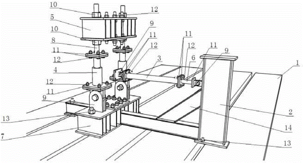
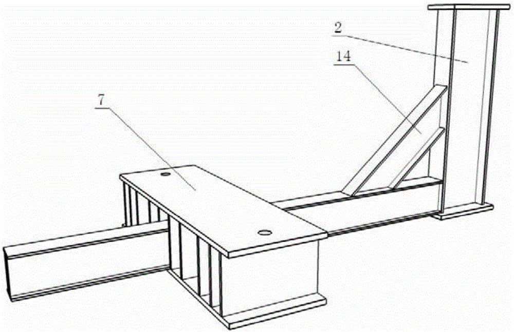
[0014] Specific implementation mode one: combine Figure 1 to Figure 6 Describe this embodiment mode, a kind of loading device that is used for space-assembled semi-rigid joint test in this embodiment mode includes L-shaped reaction force frame 2, horizontal hydraulic jack 3, fixed frame 7, reaction force beam 5 and two vertical The hydraulic jack 4, the L-shaped reaction frame 2 is vertically fixed on the upper surface of the trough 1, the horizontal end of the L-shaped reaction frame 2 is vertically fixed with a fixed frame 7, and the upper end of the fixed frame 7 is provided with a reaction beam 5 , two vertical hydraulic jacks 4 are arranged in parallel between the fixed frame 7 and the reaction beam 5, the lower end of the vertical hydraulic jack 4 is rotatably connected with the upper end surface of the fixed frame 7 through a hinge mechanism 9, and the upper end of the vertical hydraulic jack 4 An anchor rod 8 is fixedly connected, the upper end of the anchor rod 8 is ...

specific Embodiment approach 2

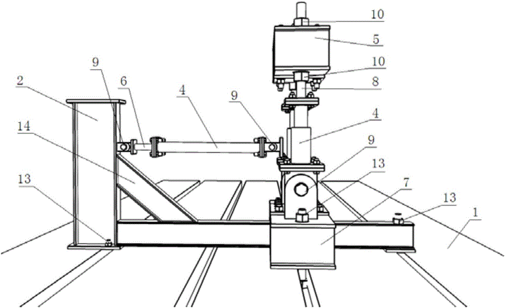
[0016] Specific implementation mode two: combination figure 1 , figure 2 with Figure 4 Describe this embodiment, the upper end of the anchor rod 8 in this embodiment is vertically inserted on the reaction beam 5 , and the upper and lower ends of the reaction beam 5 are fixedly connected to the anchor rod 8 through lock nuts 10 . Other compositions and connection methods are the same as those in Embodiment 1.

[0017] This design makes the reaction beam 5 slide along the length direction of the anchor rod 8, and after reaching the predetermined position, the position of the reaction beam 5 is locked and fixed by the lock nut 10, so that the position of the reaction beam 5 meets the requirements of different node heights. The loading scheme is flexible in practicability, and is suitable for the test of studying the mechanical properties of the assembled semi-rigid joint under the joint action of axial force and bending moment.

specific Embodiment approach 3

[0018] Specific implementation mode three: combination figure 1 , figure 2 with Figure 5 This embodiment will be described. A force sensor 6 is provided between the front end of the horizontal hydraulic jack 3 and the hinge mechanism 9 in this embodiment. Other compositions and connection modes are the same as those in Embodiment 1 or 2.

[0019] Such a design can monitor the magnitude of the applied force in the horizontal direction in real time and accurately control the time shear force.


PUM


Abstract

The invention discloses a loading device used for a space fabricated type semi-rigid joint test, and relates to test loading devices. The invention aims at solving the problems that an existing loading test can only be conducted through a traditional force loading machine and simultaneous loading of axial force and bending moment can not be achieved. The loading device for the space fabricated type semi-rigid joint test comprises an L-shaped counter-force support, a horizontal hydraulic jack, a fixed support, a counter-force beam and two vertical hydraulic jacks, wherein the fixed support is vertically and fixedly connected to a horizontal end of the L-shaped counter-force support, the upper end of the fixed support is provided with the counter-force beam, the two vertical hydraulic jacks are arranged between the fixed support and the counter-force beam in a parallel mode, the lower ends of the vertical hydraulic jacks are rotationally connected to the upper end face of the fixed support through an articulated mechanism, anchor bolts are fixedly connected to the upper ends of the vertical hydraulic jacks, and the upper ends of the anchor bolts are fixedly connected to the counter-force beam, the inner side of the vertical end of the L-shaped counter-force support is vertically provided with the horizontal hydraulic jack, and the front end of the horizontal hydraulic jack is rotationally connected to the L-shaped counter-force support through the articulated mechanism. The loading device used for the space fabricated type semi-rigid joint test is used for joint loading tests.

Description

technical field [0001] The invention relates to a test loading device, in particular to a loading device for a space-assembled semi-rigid node test. Background technique [0002] Single-layer reticulated shells have gradually become a hot spot and trend in the field of architecture. This type of building can not only meet diverse use requirements, but also rely on its strong visual expression and high flexibility in modeling, it is the future development of space grid structures. an important direction. As a key component of the space lattice structure, the steel consumption of nodes accounts for a large proportion of the total steel consumption of the space lattice structure, and its stiffness has a significant impact on the bearing capacity of the space lattice structure. The joints in the single-layer reticulated shell mainly bear the joint action of axial force and bending moment, so it is very important to study the mechanical properties of the joints under this stress...

Claims


Application Information

Patent Timeline
Patent Type & Authority Applications(China)
IPC IPC(8): G01N3/02G01N3/12G01N3/20
CPCG01N3/02G01N3/12G01N3/20G01N2203/0048G01N2203/0019G01N2203/0023
Inventor 马会环马越洋支旭东范峰
Owner HARBIN INST OF TECH
Why Eureka
Try Eureka