
Urban traffic carbon emission measurement and calculation system, and measurement and calculation method

A technology of emissions and transportation carbon, which is applied in the field of urban transportation carbon emission measurement and calculation system, can solve the problems of difficult policy simulation and evaluation, and the inability to reflect the impact of policy macroeconomic structure, etc.

Pending Publication Date: 2017-04-26
SHANGHAI MUNICIPAL ENG DESIGN INST GRP
View PDF3 Cites 29 Cited by
  • Summary
  • Abstract
  • Description
  • Claims
  • Application Information

AI Technical Summary

Problems solved by technology

The LEAP system is a typical "bottom-up" energy-environment model, which is often used to calculate energy consumption demand and corresponding pollution emissions. The LEAP system has a powerful scenario management system, and its core is the scenario analysis method, which can help create Various preset scenarios are used in the prediction and analysis of energy emissions, but they also have certain limitations. The technology model represented by the LEAP system is essentially a partial equilibrium model. Since it does not include an economic module, all macroeconomic and structural variables are It needs to be determined exogenously, so it cannot reflect the impact of policies on the macroeconomic structure. For economic policies, due to the exogenous nature of economic variables, there are certain difficulties in policy simulation and evaluation

Method used


Image

  • Urban traffic carbon emission measurement and calculation system, and measurement and calculation method
  • Urban traffic carbon emission measurement and calculation system, and measurement and calculation method
  • Urban traffic carbon emission measurement and calculation system, and measurement and calculation method

Examples


Embodiment Construction

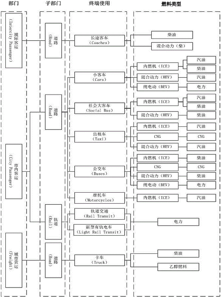
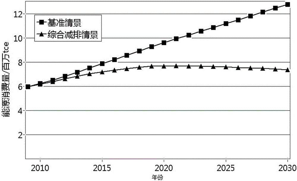
[0114] based on the following Figure 1 ~ Figure 4 , specifically explain the preferred embodiment of the present invention.

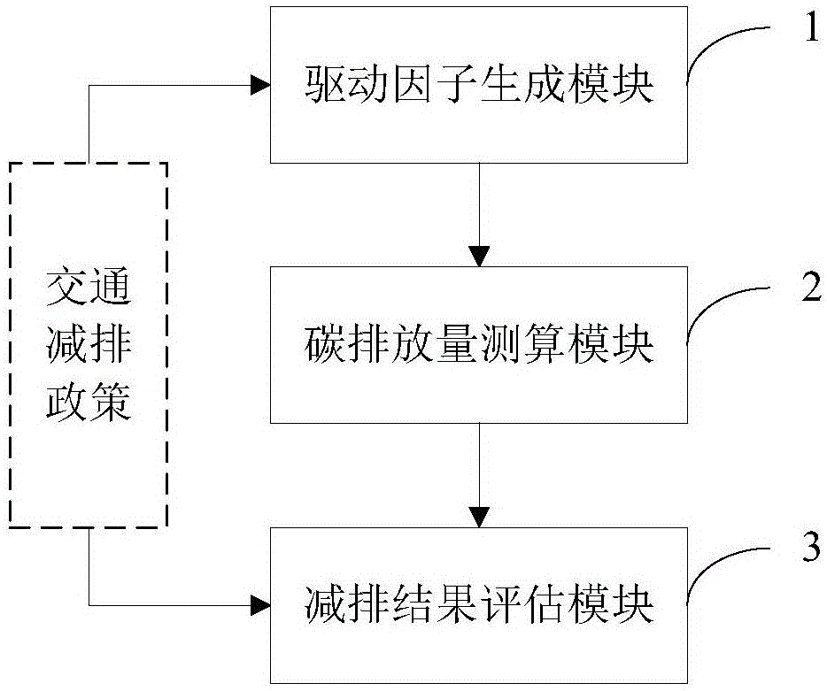
[0115] Such as figure 1 As shown, the present invention provides a system for measuring and calculating urban traffic carbon emissions, comprising:

[0116] The driving factor generation module 1 is used to extract and generate driving factors according to various traffic emission reduction policies;

[0117] The carbon emission measurement module 2 is used to calculate the energy consumption of vehicles based on each fuel type according to the driving factors, as well as the urban traffic carbon emissions and air pollutant emissions;

[0118] Emission reduction result evaluation module 3 is used to evaluate the emission reduction effects of various traffic emission reduction policies based on urban traffic carbon emissions and air pollutant emissions.

[0119] In this embodiment, the driving factor generation module 1 uses a system dynamics model, an...


PUM


Abstract

The invention discloses an urban traffic carbon emission measurement and calculation system, and an urban traffic carbon emission measurement and calculation method. The urban traffic carbon emission measurement and calculation system comprises a driving factor generating module, a carbon emission measurement and calculation module and an emission reduction outcome evaluation module, wherein the driving factor generating module is used for extracting and generating driving factors according to various traffic emission reduction policies; the carbon emission measurement and calculation module is used for calculating energy consumption according to the driving factors, and calculating urban traffic carbon emission and atmospheric pollutant emission according to the energy consumption; and the emission reduction outcome evaluation module is used for evaluating emission reduction effects of the traffic emission reduction policies according to the urban traffic carbon emission and atmospheric pollutant emission. On the basis of fully analyzing the traffic emission reduction policies and combining with an LEAP model, the urban traffic carbon emission measurement and calculation system is established, scattered output data of the traditional model is integrated into a visual index, namely, the carbon emission, so that the carbon emission is liable to be used by decision makers directly, and the effective evaluation index and method are provided for the decision-making of policy support strength and time span.

Description

technical field [0001] The invention relates to a system and a method for measuring and calculating urban traffic carbon emissions. Background technique [0002] Urban low-carbon transportation policy evaluation is to analyze the transportation carbon emissions under different preset policies, and to evaluate the effects of various policies. This type of policy evaluation generally requires the use of modeling and other means to transform specific policy descriptions into quantitative analysis parameters, and scientifically and quantitatively predict the total energy demand and energy consumption structure of urban transportation. Finally, the carbon emission coefficients corresponding to different energy sources are obtained. Urban transport carbon emissions. Therefore, the core part of low-carbon transport policy evaluation is to forecast the energy demand of urban transport. [0003] At present, the main methods for quantitative forecasting of energy carbon emission dem...

Claims


Application Information

Patent Timeline
IPC IPC(8): G06Q10/04G06Q50/26
CPCG06Q10/04G06Q50/26Y02A90/10
Inventor 包瑨
Owner SHANGHAI MUNICIPAL ENG DESIGN INST GRP
Learn More