a power divider

A technology of power divider and microstrip, which is applied in the direction of waveguide devices, circuits, connection devices, etc., can solve the problems of large actual size, large power divider loss, and narrow working bandwidth, so as to reduce the number, widen the bandwidth, reduce The effect of number of sessions

Active Publication Date: 2022-02-25
XIAN YIPU COMM TECH
View PDF6 Cites 0 Cited by
  • Summary
  • Abstract
  • Description
  • Claims
  • Application Information

AI Technical Summary

Problems solved by technology

[0003] The invention provides a power divider that satisfies the existing ultra-wideband communication system, and solves many defects of the existing power divider, such as large loss, large actual size, narrow working bandwidth, etc.

Method used


Image

  • a power divider
  • a power divider
  • a power divider

Examples


Embodiment Construction

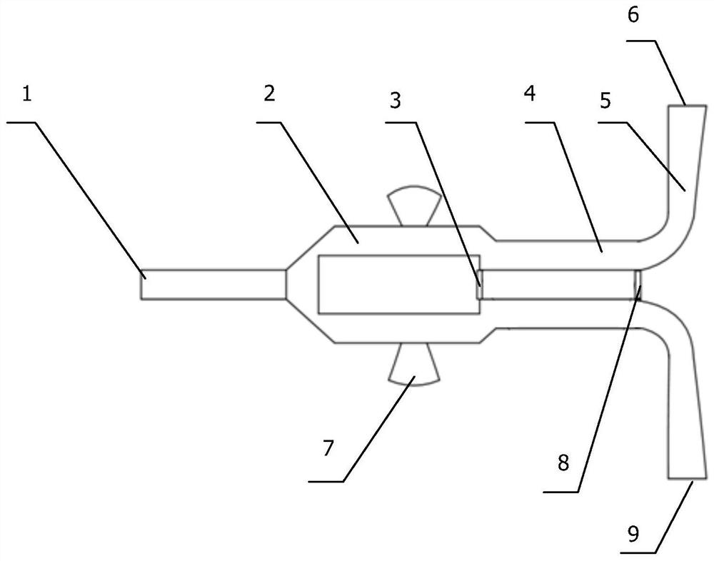
[0022] see figure 1 1. The structure of the specific embodiment of the present invention is a two-section bisecting power divider. Including two sets of microstrip impedance lines, which share one input port 1, the microstrip impedance line includes the first section of microstrip impedance line 2, the second section of microstrip impedance line 4 and the gradient microstrip line 5, the first section of microstrip impedance line A first isolation resistor 3 is connected between the line 2 and the second section of the microstrip impedance line 4, and a microstrip line unit 7 is connected in parallel to the first section of the impedance line 2, and the microstrip line unit 7 is fan-shaped. The tapered microstrip line 5 is connected to the output port of the second section of the microstrip impedance line 4 , and a second isolation resistor 8 is connected between the second section of the microstrip impedance line 4 and the tapered microstrip line 5 . The widths of the first m...


PUM


Abstract

The present invention provides a power splitter that satisfies the existing ultra-wideband communication system, including microstrip impedance lines, two groups of microstrip impedance lines share one input port, and the special feature is that the microstrip impedance lines include the first One section of microstrip impedance line and the second section of microstrip impedance line, the first isolation resistor is connected between the first section of microstrip impedance line and the second section of microstrip impedance line, and the first section of microstrip impedance line is connected in parallel with a Microstrip unit. The invention solves many defects such as large loss, large actual size and narrow working bandwidth of the existing power divider.

Description

technical field [0001] The invention belongs to the technical field of ultra-wideband mobile communication, and in particular relates to a power divider. Background technique [0002] At present, ultra-wideband technology is a new and efficient communication method that can alleviate the problem of crowded frequency resources. This technology has been gradually used in the new generation of wireless communication technologies such as WLAN and GPS. The power divider is a common passive module in the communication system. The traditional equal-divided power divider is mainly composed of multiple quarter-wavelength impedance lines. There are resistor terminals at the nodes of each impedance line. The more nodes used , the more the isolation resistance is, the correspondingly wider bandwidth and better isolation can be obtained. However, increasing the resistance will increase the parasitic loss, and increasing the number of nodes will increase the component size. Therefore, t...

Claims


Application Information

Patent Timeline
Patent Type & Authority Patents(China)
IPC IPC(8): H01P5/16
CPCH01P5/16
Inventor 苏贞霞
Owner XIAN YIPU COMM TECH
Why Eureka
Try Eureka