Automatic wire-stripping machine

A technology of automatic wire stripping and driving mechanism, which is applied in the direction of line/collector parts, electrical components, circuits, etc. It can solve the problems of jagged cutting of insulating sleeves, damage to blades, and inconvenient operation, so as to avoid jagged Phenomenon, the effect of overcoming damage

Pending Publication Date: 2017-04-26
JIESHOU XUNLIDA ELEVATOR CO LTD
View PDF0 Cites 3 Cited by
  • Summary
  • Abstract
  • Description
  • Claims
  • Application Information

AI Technical Summary

Problems solved by technology

[0002] When the wires are connected, the length cutting and the stripping of the wire ends are basically done manually. The operator first cuts off the wires, and then strips the wire ends of the wires with wire strippers. The above-mentioned manual operation is extremely inconvenient. , and the wire connection is not stable enough
[0003] In order to solve the above problems, an automated wire stripping device is used in the prior art. The wire stripping device includes a casing and a wire inlet device, a wire conduit, a knife rest assembly, and a wire outlet device arranged on the casing. The device clamps the wires through the outer wall of a pair of pressure rollers. When the pressure rollers rotate synchronously under the drive of the electrodes, the wires are driven to feed the tool holder assembly. The diameter of the wire tube is suitable for the wires. The wire is sent to the cutter part of the knife assembly; the knife holder assembly includes a knife holder and an upper blade and a lower blade arranged on the knife holder, and the upper blade reciprocates relative to the lower blade under the drive of the driving device The relative movement of the upper blade and the lower blade is used to cut the insulation tube of the wire and cut the wire. The outlet device clamps the insulation tube of the wire through the outer sidewall of a pair of pressure rollers. The wire stripping action is realized by moving the insulating sleeve away from the direction of the knife holder; the blade of the insulating sleeve used to cut the wire and the blade used to cut the wire in the above-mentioned wire stripping machine are the same blade, and the insulating sleeve is made of plastic material. However, the texture of the wire itself is relatively rigid. In this way, if a blade suitable for cutting soft objects is used to cut rigid objects, it is very easy to cause damage to the blade, and the phenomenon of tow scatter is likely to occur at the cutting position; When the blade of the object is used to cut soft objects, it is easy to cause the cutting part of the insulating sleeve to be jagged.

Method used


Image

  • Automatic wire-stripping machine
  • Automatic wire-stripping machine
  • Automatic wire-stripping machine

Examples


Embodiment Construction

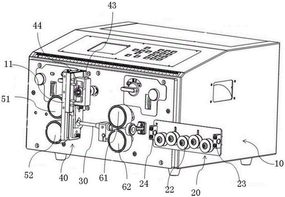
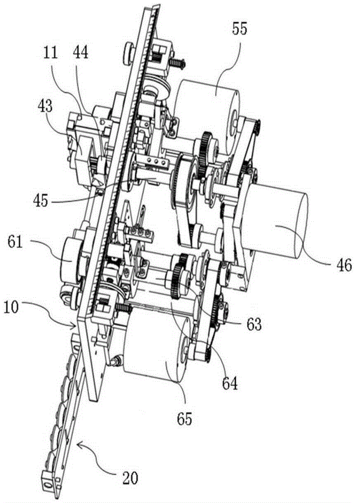
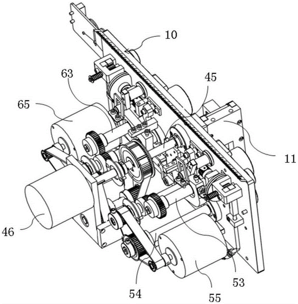
[0011] combine Figure 1 to Figure 4 , the present invention is further described:

[0012] An automatic wire stripping machine, comprising a wire inlet unit 20 arranged on a casing 10, the wire outlet end of the wire inlet unit 20 is connected to the wire conduit 30, and the outlet end of the wire conduit 30 is connected to the feed end of the knife holder assembly 40 Connecting, the discharge end of the knife rest assembly 40 is connected with the feed end of the outlet unit 50, and the knife rest assembly 40 includes a first cutter body 41 and a second cutter body arranged at the position of the discharge end of the conduit 30 42. The first and second cutter bodies 41 and 42 are respectively provided with first and second through holes 411 and 412 through which the power supply wires pass, and the edge positions of the first and second through holes 411 and 412 are set as The cutting blade, the first cutter body 41 and / or the second cutter body 42 are connected with a driv...


PUM


Abstract

The invention relates to an automatic wire-stripping machine. The automatic wire-stripping machine comprises a wire feeding unit arranged on a housing. The leading-out end of the wire feeding unit is connected with a wire conduit, and the discharge end of the wire conduit is connected with the feed end of a tool holder assembly. The discharge end of the tool holder assembly is connected with the feed end of a wire leading-out unit. The tool holder assembly comprises a first tool body and a second tool body, wherein the first tool body and the second tool body are positioned at the discharge end of the wire conduit. The first tool body and the second tool body are respectively and correspondingly provided with a first through hole and a second through hole, wherein the two through holes are used for a power supply line to pass through. The edges of the hole walls of the first and second through holes are designed to be cutting blades. The first tool body and/or the second tool body are/is connected with a driving mechanism. The driving mechanism drives the first tool body to get further from the second tool body or get closer to the second tool body. The cutting blades can be blades used for cutting rigid objects and can also be blades used for cutting soft objects. Therefore, the defects in the prior art that the blade of a cutter assembly is damaged when cutting wires and the strand diffusing phenomenon occurs at the cutting position of a wire can be overcome. In addition, the saw tooth-like phenomenon is prevented from occurring at the cutting position of a wire insulating sleeve.

Description

technical field [0001] The invention relates to the technical field of wire outer layer stripping, in particular to an automatic wire stripping machine. Background technique [0002] When the wires are connected, the length cutting and the stripping of the wire ends are basically done manually. The operator first cuts off the wires, and then strips the wire ends of the wires with wire strippers. The above-mentioned manual operation is extremely inconvenient. , and the wire connection is not stable enough. [0003] In order to solve the above problems, an automated wire stripping device is used in the prior art. The wire stripping device includes a casing and a wire inlet device, a wire conduit, a knife rest assembly, and a wire outlet device arranged on the casing. The device clamps the wires through the outer wall of a pair of pressure rollers. When the pressure rollers rotate synchronously under the drive of the electrodes, the wires are driven to feed the tool holder ass...

Claims


Application Information

Patent Timeline
Patent Type & Authority Applications(China)
IPC IPC(8): H01R43/28
Inventor 贺杰贺明郑士海贺文静
Owner JIESHOU XUNLIDA ELEVATOR CO LTD
Why Eureka
Try Eureka