Unlock instant, AI-driven research and patent intelligence for your innovation.

A delay unit and a ring voltage-controlled oscillator comprising the delay unit

A delay unit and adjustment unit technology, which is applied in the direction of electrical components, electric pulse generator circuits, logic circuits to generate pulses, etc., can solve problems such as small tuning range, flicker noise, and circuits that cannot reach full-swing output, and achieve gain Controllable, wide tuning range, good phase noise characteristics

Active Publication Date: 2021-01-01
HUNAN GOKE MICROELECTRONICS
View PDF9 Cites 0 Cited by
  • Summary
  • Abstract
  • Description
  • Claims
  • Application Information

AI Technical Summary

Problems solved by technology

[0005] In the prior art, due to the existence of the tail current source of the fully differential ring voltage-controlled oscillator, the circuit cannot reach the full-swing output. At the same time, the existence of the tail current will introduce flicker noise, which will deteriorate the phase noise at low frequencies. Can affect the phase noise performance of the oscillator at low frequencies
[0006] At the same time, in order to control the oscillation frequency of the ring voltage-controlled oscillator, the existing method is to add a switched capacitor. Although this method can control the oscillation frequency and achieve full swing output, the tuning range of this control method is relatively small.
[0007] Since the gain of the ring voltage-controlled oscillator is closely related to the transfer function of the entire PLL, a large change in the gain of the oscillator will cause a large change in the transfer function of the PLL, which will make the entire PLL unstable

Method used


Image

  • A delay unit and a ring voltage-controlled oscillator comprising the delay unit
  • A delay unit and a ring voltage-controlled oscillator comprising the delay unit
  • A delay unit and a ring voltage-controlled oscillator comprising the delay unit

Examples


Embodiment Construction

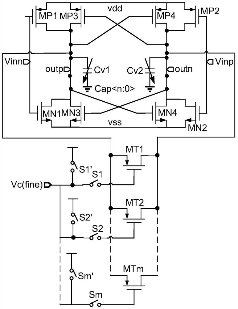
[0033] like Figure 1 to Figure 5As shown, the delay unit of the present invention includes m adjustment units, and each adjustment unit includes corresponding adjustment transistors MT1, MT2, MTm, first MOS switches S1, S2, Sm and second MOS switches S1', S2', Sm' , the adjustment transistors MT1, MT2, and MTm are P-type transistors; for each adjustment unit, the positive pole of the power supply vdd passes through the second MOS switches S1', S2', Sm', the first MOS switches S1, S2, Sm and adjusts in turn The gates of the tubes MT1, MT2, and MTm are connected, and the adjustment voltage input terminal Vc (fine) is connected between the first MOS switches S1, S2, Sm and the second MOS switches S1', S2', Sm'; also includes the first The switch capacitor Cv1, the second switch capacitor Cv2, the push-pull input pair connected by the first N-type transistor MN1, the second N-type transistor MN2, the first P-type transistor MP1 and the second P-type transistor MP2, and the third ...


PUM


Abstract

The invention discloses a delay unit and a ring voltage-controlled oscillator including the delay unit. The delay unit comprises at least two adjusting units, each adjusting unit comprises an adjusting tube, a first MOS switch, and a second MOS switch, a power supply positive electrode is connected with a grid electrode of the adjusting tube through the second MOS switch and the first MOS switch in sequence, an adjusting voltage input terminal is connected between the first MOS switch and the second MOS switch, the delay unit also comprises a first switch capacitor, a second switch capacitor, a push-pull input pair transistor formed by connection of a first N-type transistor, a second N-type transistor, a first P-type transistor and a second P-type transistor, and a latch formed by connection of a third N-type transistor, a fourth N-type transistor, a third P-type transistor and a fourth P-type transistor, and a first input terminal of the delay unit is connected between a grid electrode of the first P-type transistor and a grid electrode of the first N-type transistor. According to the delay unit and the ring voltage-controlled oscillator, the gain is controllable, full-swing output can be realized, the tuning range is wide, and the phase noise characteristic is good.

Description

technical field [0001] The invention belongs to the technical field of integrated circuits, in particular to a delay unit and a ring voltage-controlled oscillator comprising the delay unit. Background technique [0002] Voltage Controlled Oscillator (VCO, Voltage Controlled Oscillator) is an important unit in the fields of communication and electronics. Its oscillation frequency can change with the external control voltage. It is widely used in phase-locked loop, clock recovery and frequency synthesis circuits. Among them, the VCO has become a key component that affects the performance of the entire system. [0003] As a kind of voltage-controlled oscillator, the ring voltage-controlled oscillator includes at least two delay units, and the delay units are connected to form a ring structure connected end to end. Different stages can be easily obtained by adjusting the number of delay units in the oscillator. phase of a series of clock signals. [0004] Ring oscillators can ...

Claims


Application Information

Patent Timeline
Patent Type & Authority Patents(China)
IPC IPC(8): H03K3/013H03K3/03
CPCH03K3/013H03K3/0315
Inventor 姜黎李天望周述康希邓春惠
Owner HUNAN GOKE MICROELECTRONICS