
PLL circuit with low stray fast lock

A fast-locking, low-spur technology, applied to electrical components, power automatic control, etc., can solve the problems of large charge pump CP current mismatch, affecting system stability, and lock-up time, so as to achieve overall performance improvement and reference miscellaneous Dispersion reduction, elimination of delay mismatch effects

Active Publication Date: 2020-05-15
UNIV OF SCI & TECH OF CHINA
View PDF1 Cites 0 Cited by
  • Summary
  • Abstract
  • Description
  • Claims
  • Application Information

AI Technical Summary

Problems solved by technology

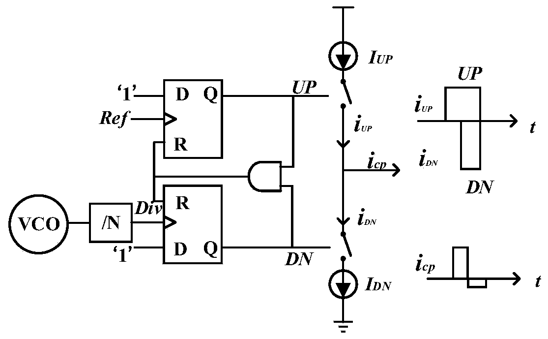
[0017] It can be seen from formula (4) that the traditional CPPLL can sacrifice phase margin and bandwidth in order to obtain a better reference spur, but this will affect the stability of the system and the locking time
At the same time, reference spurs can also be reduced by reducing the current mismatch of the charge pump. However, since the PFD / CP of the traditional charge pump CPPLL must have a static mismatch, this leads to the existence of ripples caused by the control voltage. With the progress of the process, it will become more obvious, because the effects such as channel length modulation of the advanced process are more obvious, which will lead to a larger charge pump CP current mismatch

Method used


Image

  • PLL circuit with low stray fast lock
  • PLL circuit with low stray fast lock
  • PLL circuit with low stray fast lock

Examples


Embodiment Construction

[0043] The technical solutions in the embodiments of the present invention will be clearly and completely described below in conjunction with the accompanying drawings in the embodiments of the present invention. Obviously, the described embodiments are only some of the embodiments of the present invention, not all of them. Based on the embodiments of the present invention, all other embodiments obtained by persons of ordinary skill in the art without making creative efforts belong to the protection scope of the present invention.

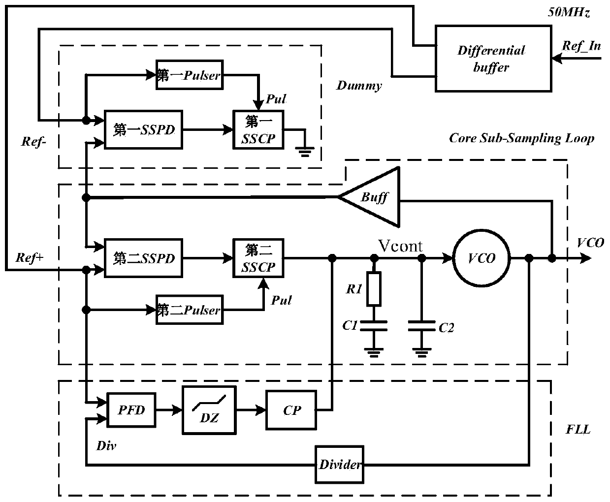
[0044] image 3It is a schematic structural diagram of a phase-locked loop circuit with low spurious fast locking provided by the embodiment of the present invention. Such as image 3 As shown, it mainly includes: differential buffer (Differential buffer), Dummy sampler circuit, sub-sampling loop (Core Sub-Sampling Loop) and frequency-locked loop FLL (Frequency-locked Loop); wherein,

[0045] The differential buffer converts the reference signal ...


PUM


Abstract

The invention discloses a phase-locked loop low in stray and quick in locking. The phase-locked loop eliminates strays caused by delayed mismatching of a phase frequency detector of a traditional charge pump phase-locked loop and current mismatching of the charge pump, and enables interference of adjacent channels of a radio communication transceiver system to be greatly reduced. Through adoption of a Dummy sampler circuit, reference strays are reduced to a great extent. Moreover, the locking speed can be increased through increases of the current of a phase-locked loop charge pump, so that the overall performance of the phase-locked loop can be improved comprehensively.

Description

technical field [0001] The invention relates to the technical field of radio frequency integrated circuits, in particular to a phase-locked loop circuit with low spurious and fast locking. Background technique [0002] Many applications, such as up-down conversion of wireless communication systems, sampling of high-speed analog-to-digital converters ADC (Analog-to-Digital Converters), high-speed serial data communication Serdes, etc., require a stable high-purity clock and intrinsic signals. The spectral purity of the clock source has a significant impact on the overall system. For communication systems, in order to achieve low noise, the clock source must achieve low spurs, because spurs can cause spectral aliasing of adjacent signals. For high-speed ADCs, spurs translate into deterministic jitter, reducing the signal-to-noise ratio. [0003] In a wireless communication transceiver, a phase-locked loop circuit PLL (Phase-locked Loop) provides an accurate intrinsic clock s...

Claims


Application Information

Patent Timeline
Patent Type & Authority Patents(China)
IPC IPC(8): H03L7/085
CPCH03L7/085
Inventor 曾铭王宇涛林福江
Owner UNIV OF SCI & TECH OF CHINA
Learn More