A kind of synchronous clock reference source and synchronous clock reference generation method

A technology for synchronizing clocks and generating methods, applied in the direction of electrical components, automatic power control, etc., can solve the problems of logic driver noise, complex circuits, complex peripheral circuits, etc., to reduce device costs, eliminate harmonic noise, and reduce the number of devices. Effect

Active Publication Date: 2018-08-10
THE 41ST INST OF CHINA ELECTRONICS TECH GRP
View PDF4 Cites 0 Cited by
  • Summary
  • Abstract
  • Description
  • Claims
  • Application Information

AI Technical Summary

Problems solved by technology

On the one hand, the peripheral circuits of such active frequency multiplication or frequency division devices are relatively complex and occupy a large space. At the same time, active devices will introduce certain noise effects
On the other hand, high-performance clock generators are costly, have many package pins, and complex circuits
[0007] (2) In order to eliminate out-of-band noise interference, especially noise such as harmonics and sub-harmonics, the clock source needs to design a passband filter for filtering. Using a matching network filter usually effectively eliminates the out-of-band remote noise, but due to the filtering The design of the filter will be affected by the characteristics of the device itself such as capacitors and inductors. It is difficult to design a filter with a very narrow bandwidth. Therefore, it is difficult to filter out the near-end noise, which will reduce the quality of the final sampling clock.
When selecting the logic device to drive the converter, it usually cannot provide the highest performance level. According to relevant statistics, the jitter of most series of logic devices is about 200fs or more, and the logic driver will also introduce noise.

Method used


Image

  • A kind of synchronous clock reference source and synchronous clock reference generation method
  • A kind of synchronous clock reference source and synchronous clock reference generation method
  • A kind of synchronous clock reference source and synchronous clock reference generation method

Examples


Embodiment Construction

[0043] The following will clearly and completely describe the technical solutions in the embodiments of the present invention with reference to the accompanying drawings in the embodiments of the present invention. Obviously, the described embodiments are only some, not all, embodiments of the present invention. Based on the embodiments of the present invention, all other embodiments obtained by persons of ordinary skill in the art without making creative efforts belong to the protection scope of the present invention.

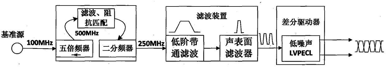
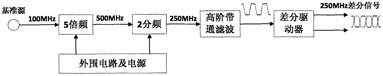
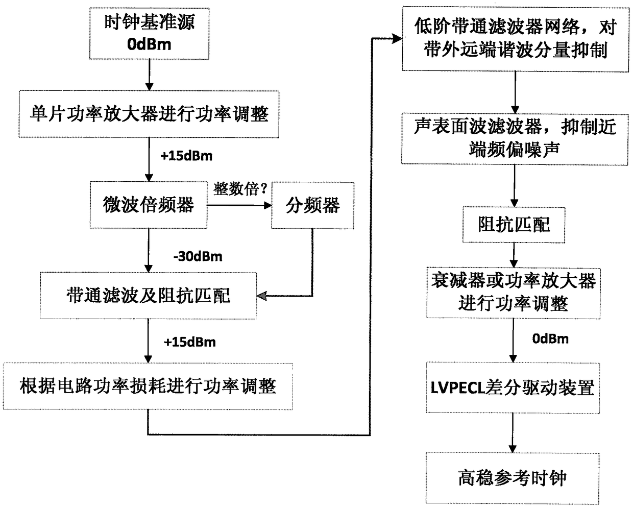
[0044]In the field of electronic measurement, measuring instruments need to provide a stable and reliable high-performance clock reference source when converting analog signals and digital signals (A / D, D / A), and the clock frequency can reach up to several hundred MHz. In general, the time base reference frequency provided by the whole machine has a high performance index and a low frequency, so it needs to be multiplied or divided to generate a clock source. ...


PUM


Abstract

The present invention proposes a synchronous clock reference source, including: a frequency multiplier device, a filter device, and a level conversion output device; the frequency multiplier device completes the frequency multiplication processing of the reference source input to obtain the required clock frequency source; The filtering device is divided into two stages, the first-stage device adopts a matching network filter to filter out the far-end harmonic component of the reference source signal, and the second-stage device adopts a surface acoustic wave filter to further eliminate near-end noise of the signal to obtain a high-quality clock signal; The level conversion output device uses a single-ended sine wave to differential level standard chip to perform level conversion on the clock signal. The invention adopts the clock reference source of the instrument itself as a reference source, solves the problem of asynchronous phase error, and at the same time solves the interference of harmonic noise to cascaded circuits, simplifies the circuit structure, reduces the use of complex devices, and improves work efficiency.

Description

technical field [0001] The invention relates to the technical field of testing, in particular to a synchronous clock reference source, and also to a synchronous clock reference generation method. Background technique [0002] The source of the clock reference source of the analog-to-digital converter in the measuring instrument can be divided into a fixed frequency source and an external reference source. The fixed clock source is a fixed time reference source for the whole machine. Its operating frequency is usually 10MHz, which is extremely stable and traceable. It is also the source of an intermediate time reference source or a series of reference sources, but the frequency is low. The sampling clock is obtained after frequency multiplication processing, but at the same time, harmonic noise interference is increased. The external reference source does not use the clock reference of the whole machine, but directly uses a fixed-frequency crystal clock oscillator. Generally...

Claims


Application Information

Patent Timeline
Patent Type & Authority Patents(China)
IPC IPC(8): H03L7/083
Inventor 刘强朱伟李伟
Owner THE 41ST INST OF CHINA ELECTRONICS TECH GRP
Why Eureka
Try Eureka