
Patsnap Eureka
For R&D, Patsnap Eureka makes reading and utilizing patents & technical documents easy.
Patsnap Eureka AIR
Designed for self-driven R&D workflows. Generate viable solutions, solve complex R&D challenges, empower your innovation with AI.

Patsnap Eureka Materials
Designed for material experts only. Revolutionize your material R&D, from search, analyze, to developing new materials.

TechResearch
Generate reliable direction feasibility study reports for your R&D in just a few steps.

TechSeek
Discover and master advanced knowledge NOW. Basics, ideas, possibilities, all at once.

TechMind
As an expert in R&D Theories, TechMind can generates customized viable solutions instantly.

TechRisk
Analyze your overall solution with one click, know your potential R&D risks in advance.

TechMonitor
Get weekly tech updates, stay abreast of the latest tech innovations and key insights.
Sand unloading device
A sand hopper and mounting plate technology, applied in the field of machinery and equipment, can solve problems such as occasional occurrence, damage to tape, and splitting, and achieve the effect of reducing maintenance workload and prolonging life.
- Summary
- Abstract
- Description
- Claims
- Application Information
AI Technical Summary
Problems solved by technology
Method used
Image

Examples
specific Embodiment approach
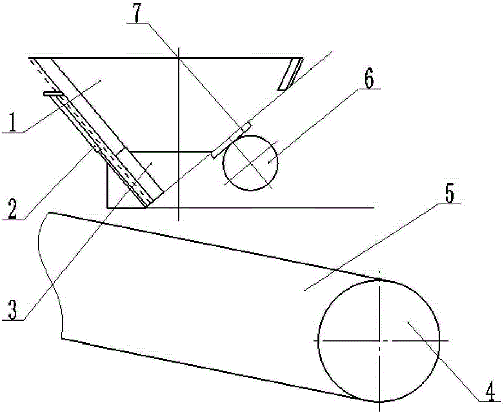
[0012] Examples, see attached figure 1 , a sand unloading device, including a sand bucket 1, a mounting plate 2, a trough 3, a pulley 4, a conveyor belt 5, a driving motor 6 and a motor seat 7, wherein the sand bucket 1 is welded by section steel , the lower part of the sand bucket 1 adopts an angle of 40°, the left side of the sand bucket 1 is provided with an outlet, the installation plate 2 is fixedly installed on the left side of the sand bucket 1 and can slide along the sand bucket 1, and the hopper 3 is fixedly installed on the At the outlet of the sand bucket 1, the drive motor 6 is fixedly installed on the motor base 7, the motor base 7 is fixedly installed on the right end of the sand bucket 1, and the two ends of the conveyor belt 5 are installed on the pulley 4 and are located in the sand bucket. 1 directly below.
[0013] Preferably, the mounting plate 2 is automatically adjusted by a cylinder.
[0014] Preferably, the vibration force of the drive motor 6 is adju...
PUM
 Abstract
Description
Claims
Application Information
 - R&D Engineer
- R&D Manager
- IP Professional
- Industry Leading Data Capabilities
- Powerful AI technology
- Patent DNA Extraction
Browse by: Latest US Patents, China's latest patents, Technical Efficacy Thesaurus, Application Domain, Technology Topic, Popular Technical Reports.
© 2024 PatSnap. All rights reserved.Legal|Privacy policy|Modern Slavery Act Transparency Statement|Sitemap|About US| Contact US: help@patsnap.com