
Sand unloading device

A sand bucket and mounting plate technology, applied in the field of casting, can solve problems such as occasional occurrence, damaged tape, splitting, etc., and achieve the effect of reducing maintenance workload and prolonging life

Inactive Publication Date: 2018-02-16
CHANGZHOU CHANGTONG PLASTIC PIPE
View PDF0 Cites 0 Cited by
  • Summary
  • Abstract
  • Description
  • Claims
  • Application Information

AI Technical Summary

Problems solved by technology

But because there are burrs, small sprues and other pieces of scrap iron in the old sand, when the sharp corners of these scrap iron burrs are scratched on the belt of the belt conveyor, it will damage the belt or even cut it
In addition, due to the different process methods, the phenomenon of overload sand unloading still occurs from time to time

Method used


Image

  • Sand unloading device

Examples


specific Embodiment approach

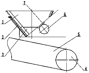
[0012] Examples, see attached figure 1 , a sand unloading device, including a sand bucket 1, a mounting plate 2, a trough 3, a pulley 4, a conveyor belt 5, a driving motor 6 and a motor seat 7, wherein the sand bucket 1 is welded by section steel , the lower part of the sand bucket 1 adopts an angle of 40°, the left side of the sand bucket 1 is provided with an outlet, the installation plate 2 is fixedly installed on the left side of the sand bucket 1 and can slide along the sand bucket 1, and the hopper 3 is fixedly installed on the At the outlet of the sand bucket 1, the drive motor 6 is fixedly installed on the motor base 7, the motor base 7 is fixedly installed on the right end of the sand bucket 1, and the two ends of the conveyor belt 5 are installed on the pulley 4 and are located in the sand bucket. 1 directly below.

[0013] Preferably, the mounting plate 2 is automatically adjusted by a cylinder.

[0014] Preferably, the vibration force of the drive motor 6 is adju...


PUM


Abstract

The invention discloses a sand unloading device, which includes a sand bucket, a mounting plate, a trough, a pulley, a conveyor belt, a driving motor and a motor seat, and is characterized in that the sand bucket is welded by section steel, and the lower part of the sand bucket is made of 30°~50° angle, there is an outlet on the left side of the sand hopper, the installation plate is fixedly installed on the left side of the sand hopper and can slide along the sand hopper, the hopper is fixedly installed at the outlet of the sand hopper, the The drive motor is fixedly installed on the motor base, and the motor base is fixedly installed on the right end of the sand bucket, and the two ends of the conveyor belt are installed on the pulleys and are located directly below the sand bucket.

Description

technical field [0001] The invention relates to the technical field of casting, in particular to a sand unloading device. Background technique [0002] In the sand treatment section, when the sand is shaken out or sent, there will be a phenomenon that the amount of sand transported in a short period of time is too large, and sometimes the follow-up equipment will be overloaded, affecting the effect of sand treatment or causing failures. In order to avoid this phenomenon, some foundry companies have taken measures to unload sand from the sand storage hopper under the shakeout machine, that is, a section of compact cutting guide trough is added to the belt conveyor, and a limited amount of outlet is adopted at the outlet of the guide trough. , played a certain role. But because there are burrs, small sprues and other pieces of scrap iron in the old sand, when the sharp corners of these scrap iron burrs are scratched on the belt of the belt conveyor, it will damage the belt or...

Claims


Application Information

Patent Timeline
IPC IPC(8): B65D88/66B65G47/19
CPCB65D88/66B65G47/19B65G2201/045
Inventor 朱金平
Owner CHANGZHOU CHANGTONG PLASTIC PIPE
Learn More