Drilling machine for spherical outer surface of bearing outer ring

A technology of bearing outer ring and outer spherical surface, which is applied in the field of bearing processing, and can solve problems such as high cost, low labor cost, clamping deformation and damage

Inactive Publication Date: 2017-05-10
张桂春
View PDF2 Cites 8 Cited by
  • Summary
  • Abstract
  • Description
  • Claims
  • Application Information

AI Technical Summary

Problems solved by technology

The labor cost of this invention is relatively low, but the structure of the drilling device is complicated and the cost is hig

Method used


Image

  • Drilling machine for spherical outer surface of bearing outer ring
  • Drilling machine for spherical outer surface of bearing outer ring

Examples


Embodiment Construction

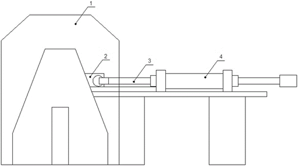
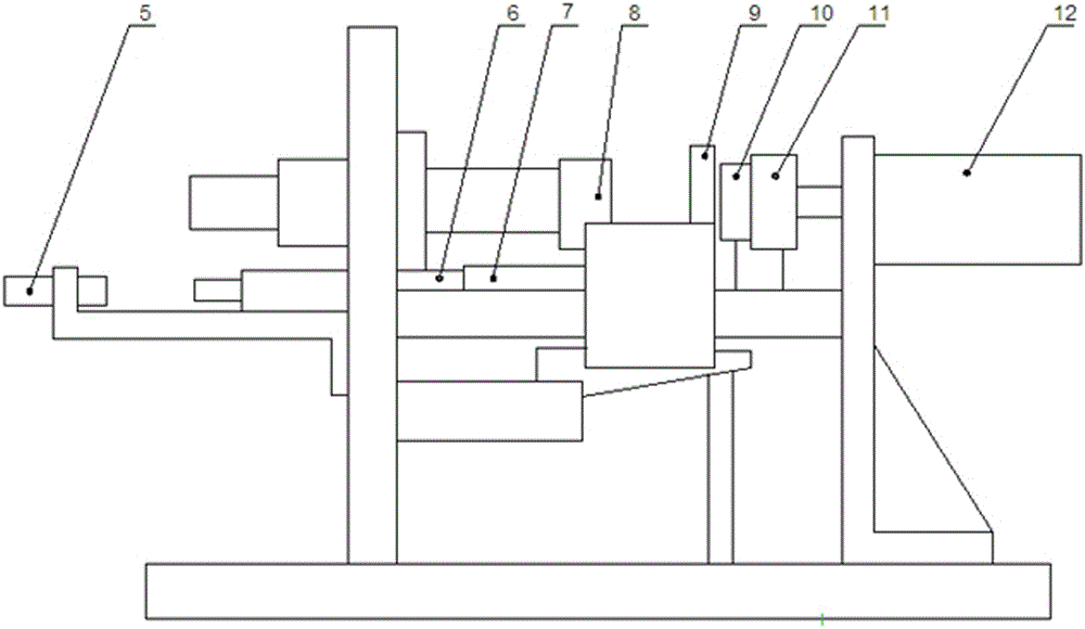
[0018] When the drilling machine 1 is working, the workpiece 10 to be drilled is delivered to the support frame 2 through the feed channel. After the workpiece 10 falls to the support frame 2, the push cylinder 4 pushes the push rod 3 to translate and drives the support frame 2 to move laterally. ; When the workpiece 10 moves to the same axis as the cylindrical boss of the movable chuck 11 and the static chuck 8, the sensor 5 touches the movement of the clamping cylinder 12, and the cylinder piston pushes the movable chuck 11 to make a linear motion, and the movable chuck 11 moves The set cylindrical boss is embedded in the outer ring of the bearing to cooperate with the clamping rod 9, and the clamped workpiece moves to the static chuck 8. When the front end of the workpiece contacts the static chuck 8, the clamping rod 9 is embedded in the static chuck 8 In the groove, the movable chuck 11 and the static chuck 8 rely on their axial positioning to perform axial positioning and...


PUM


Abstract

The invention provides a drilling machine for a spherical outer surface of a bearing outer ring. An automatic loading and unloading device, a clamping device, a drilling device and a PLC for system control are adopted to realize multi-procedure continuous automatic processing of loading, clamping, multi-directional drilling, unloading and the like. The drilling machine can well adapt to the requirements for multiple holes, multiple angles and adjustable positions of an insert bearing during drilling, and well meets the demand on precision of the insert bearing during drilling, and meanwhile, the drilling efficiency is improved.

Description

technical field [0001] The invention relates to the field of bearing processing, in particular to a drilling machine for the outer spherical surface of the bearing outer ring. Background technique [0002] When processing the ring of the bearing, in order to meet the needs of lubrication, it is often necessary to open a through hole on the outer circumferential surface of the ring to communicate with the groove on the inner surface to ensure that there is enough lubricating oil in the groove when the bearing is working, so There is a high position accuracy requirement for this hole. At present, many of the inner and outer rings of the bearing are drilled manually with a bench drill. This method has low precision, low efficiency, unstable quality and low efficiency in the drilling process, etc. question. [0003] Chinese invention patent (application number: 201320187258.8 application date: 2013.04.15) discloses a bearing ring drilling device, including a mounting plate, a s...

Claims


Application Information

Patent Timeline
IPC IPC(8): B23B41/00B23Q7/00B23B39/08
CPCB23B41/00B23B39/08B23B2215/12B23Q7/00B23Q7/006B23Q2707/00
Inventor 张桂春
Owner 张桂春
Why Eureka
Try Eureka