
Glass pressing equipment

A technology for laminating equipment and glass, applied in metal processing equipment, metal processing, manufacturing tools, etc., can solve the problems such as the change of the lamination position of the door frame and the glass, the low accuracy of manually fixing the door frame, and the influence on the quality of the glass panel of the refrigerator. To achieve the effect of providing production quality and production efficiency, good pressing quality and high pressing efficiency

Active Publication Date: 2019-02-22
钟毅
View PDF7 Cites 0 Cited by
  • Summary
  • Abstract
  • Description
  • Claims
  • Application Information

AI Technical Summary

Problems solved by technology

The problems existing in the pressing process of the existing glass panels are: firstly, due to the large size of the door frame, a large amount of labor is required to fix the door frame, which greatly reduces the glass pressing efficiency; secondly, the accuracy of manually fixing the door frame is not high enough. High, and in the process of coordinating and fixing the door frame by multiple people, it is inevitable that the door frame will shake, resulting in changes in the pressing position of the door frame and glass, which affects the quality of the refrigerator glass panel

Method used


Image

  • Glass pressing equipment
  • Glass pressing equipment
  • Glass pressing equipment

Examples


Embodiment Construction

[0028] The present invention will be further described below in conjunction with the accompanying drawings and embodiments.

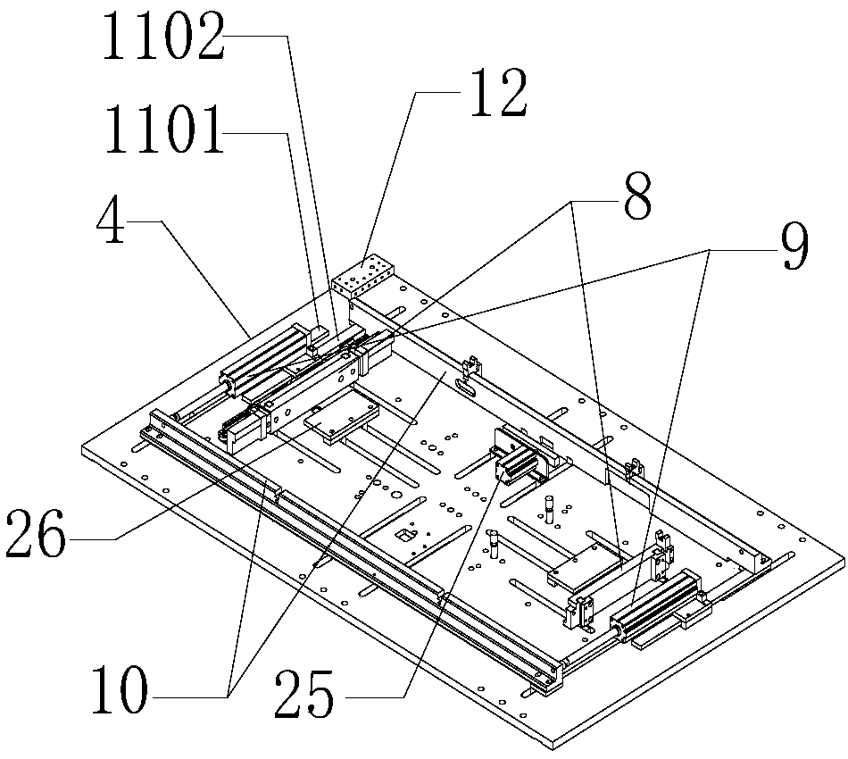
[0029] Such as figure 1 As shown, the glass pressing equipment includes an upper transmission line 1 and a lower transmission line 2 , and the upper transmission line 1 is located directly above the lower transmission line 2 . Both ends of the upper transmission line 1 and the lower transmission line 2 are equipped with a tooling circulation lifting system 3, the tooling circulation lifting system 3 includes a lifting cylinder 301, a lifting tray 302, a proximity switch and a photoelectric sensor, and the lifting tray 302 is arranged on the piston of the lifting cylinder 301. On the rod, the lifting cylinder 301 moves to drive the lifting pallet 302 to rise and fall. When the lifting tray 302 rises to be level with the upper transmission line 1, the lifting tray 302 at one end transports the unprocessed tooling board to the upper transmission line 1. ...


PUM


Abstract

The invention relates to the field of glass laminating, in particular to a glass laminating device. The glass laminating device comprises a conveying line and tool plates arranged on the conveying line. The conveying line comprises a conveying line body and conveying wheels connected with a motor. Multiple stations are arranged on the conveying line at intervals in the length direction. Each station is provided with one tool plate, and each tool plate is provided with at least one set of positioning and clamping device. Each positioning and clamping device comprises two clamping rods which are arranged in parallel, clamping air cylinders, gear and rack mechanisms and a synchronous mechanism, wherein the clamping rods move in the width direction of the corresponding tool plate, the clamping air cylinders and the gear and rack mechanisms are located between the clamping rods, the two ends of one clamping rod are connected with the clamping air cylinders correspondingly, the two clamping rods are connected through the gear and rack mechanisms at the two ends, and the two gear and rack mechanisms are connected through the synchronous mechanism. The glass laminating device can be used for rapidly and accurately fixing a door frame, the quality of a glass panel is ensured, the production efficiency of the glass panel is improved, and in addition, mixed production of various specifications of products on the device is achieved.

Description

technical field [0001] The invention relates to the field of glass pressing, in particular to glass pressing equipment. Background technique [0002] With the maturity of refrigerator technology, refrigerator companies began to work hard on refrigerator materials and craftsmanship. The original plastic panels were gradually replaced by tempered panels and glass panels, and the appearance of refrigerators became more and more fashionable. [0003] In order to save cost and product weight in existing common single-door and two-door refrigerators, the panels are mostly made of plastic. The three-door refrigerators and multi-door refrigerators mostly use stainless steel panels or glass panels. The surface of the glass panel is smooth, and its anti-fouling performance is relatively good, especially in an environment with a lot of oily smoke and water vapor in the kitchen, it is more convenient to clean. Not only that, the glass panel also has the advantages of no deformation, n...

Claims


Application Information

Patent Timeline
Patent Type & Authority Patents(China)
IPC IPC(8): B23P19/02B25B11/02
CPCB23P19/02B25B11/02
Inventor 钟毅
Owner 钟毅
Learn More