A double-layer structure vacuum suction table

A double-layer structure, vacuum suction technology, applied in the direction of workpiece clamping devices, manufacturing tools, etc., can solve the problems of large airflow energy loss, limited precision, low strength of vacuum suction table, etc.

Active Publication Date: 2018-05-01
FOSHAN SHUNDE DISTRICT YINMEI FINE HARDWARE TECH
View PDF7 Cites 0 Cited by
  • Summary
  • Abstract
  • Description
  • Claims
  • Application Information

AI Technical Summary

Problems solved by technology

In this method, because holes and grooves are processed on the honeycomb core, the strength of the honeycomb core is greatly weakened, resulting in low strength of the vacuum table.
The honeycomb core is a porous structure. When the airflow flows through the honeycomb core, there is a lot of resistance, and the energy loss of the airflow is large, resulting in weak adsorption force; the high resistance of the honeycomb core also leads to a large adsorption force near the air outlet, and far away from the air outlet. The adsorption force is small or no adsorption force, and the adsorption force of the entire suction table area is seriously uneven
The machining accuracy of the honeycomb core is limited, and its precision directly affects the flatness of the suction table, making it difficult to control the flatness of the suction table, and the precision is limited

Method used


Image

  • A double-layer structure vacuum suction table
  • A double-layer structure vacuum suction table
  • A double-layer structure vacuum suction table

Examples


Embodiment 1

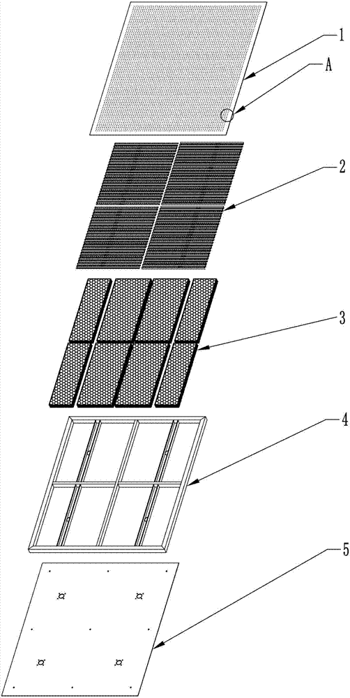
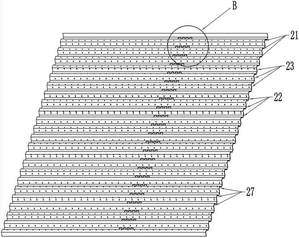
[0034] Such as Figure 5 As shown, the upper and lower end surfaces (21, 22) of the corrugated core 2 are horizontal planes. Specifically, the corrugated core 2 is composed of a plurality of trapezoidal structures 6 connected at intervals. The waist planes 61 on both sides of the surface 60 are open at the bottom. A plurality of upper step surfaces 60 spaced apart form the upper end surface 21, and the connecting surface 62 between the trapezoidal structures 6 forms the lower end surface 22. The waist plane 61 of the trapezoidal structures 6 forms the upper end surface 21. The connecting surface 23 is supported, so that the upper step surface 60 and the waist planes 61 on both sides constitute the above-mentioned ventilation area 27 .

Embodiment 2

[0036] This embodiment is basically similar in structure and principle to the above-mentioned embodiment 1, the difference is that the upper and lower end surfaces (21, 22) of the corrugated core 2 are arc-shaped end surfaces. For example: the corrugated core 2 is in a wave shape, which includes a crest section and a trough section, and a transition section connecting the crest section and the trough section, each crest section forms the upper end surface, each trough section forms the lower end surface, and each transition section forms The supporting connection surface.

[0037] In addition, in the above-mentioned Embodiment 1 and Embodiment 2, the frame 4 is surrounded by the outer profile 42, and the inside of the frame 4 is fixedly connected with the air duct profile 43, and the air duct profile 43 divides the inner area of ​​the frame into one or more than one The installation area 41 of the air duct profile 43 includes a bottom plane and side planes extending upwards an...


PUM


Abstract

The invention relates to a vacuum suction table of a double-layer structure. The vacuum suction table comprises a frame, a bottom plate, a panel and honeycomb cores; the bottom plate is provided with bottom plate suction openings and the panel is covered with small adsorption holes; the vacuum suction table is characterized in that the inner region of the frame includes air duct regions and installation regions, the air duct regions and the installation regions are independent mutually, the air duct regions are internally provided with air duct suction openings which are communicated with the bottom plate suction openings in a one-to-one correspondence mode, the installation regions correspond to the honeycomb cores one to one, and the frame is filled with corrugated cores located above the honeycomb cores, each corrugated core includes an upper end face, a lower end face and supporting connection faces, each upper end face is combined with the supporting connection faces located at the two sides of the upper end face to form an aeration area which is communicated with the corresponding air duct region, the upper end faces are connected with the panel and provided with small air holes A which are communicated with the small adsorption holes in a one-to-one correspondence mode, a part of lower end faces are in connection with the corresponding honeycomb cores in a covering mode, and the other part of the lower end faces are connected with the corresponding air duct regions. The vacuum suction table is high in strength, internal gas paths are small in windage resistance, energy loss is low, and adsorption force is large and uniform.

Description

technical field [0001] The invention relates to a double-layer structure vacuum suction table. Background technique [0002] The structure of the vacuum suction table used in the market is to fix the honeycomb core with a frame welded by profiles, and then bond the bottom plate and the panel at the bottom and face respectively. The principle is to use the honeycomb core to fill and support, and process holes and grooves on the honeycomb core to achieve that each cell of the honeycomb core is connected to each other, the bottom plate draws air, and the airflow passes through the honeycomb core to generate adsorption on the small adsorption holes of the panel. force. In this method, because holes and grooves are processed on the honeycomb core, the strength of the honeycomb core is greatly weakened, resulting in low strength of the vacuum table. The honeycomb core is a porous structure. When the airflow flows through the honeycomb core, there is a lot of resistance, and the ...

Claims


Application Information

Patent Timeline
Patent Type & Authority Patents(China)
IPC IPC(8): B25B11/00
CPCB25B11/00
Inventor 赖少山
Owner FOSHAN SHUNDE DISTRICT YINMEI FINE HARDWARE TECH
Why Eureka
Try Eureka