Novel concrete mixer

A concrete mixer and a new type of technology, which are applied to cement mixing devices, clay preparation devices, chemical instruments and methods, etc., can solve the problems of insufficient mixing of the new concrete mixer, inconvenient control of concrete usage, and inability to guarantee the strength of buildings, etc. The effect of reducing electric energy, saving materials and convenient operation

Inactive Publication Date: 2017-05-10
唐健发 +1
View PDF7 Cites 7 Cited by
  • Summary
  • Abstract
  • Description
  • Claims
  • Application Information

AI Technical Summary

Problems solved by technology

[0005] The new concrete mixer of the above invention does not mix sufficiently, so that the strength of the building using the concrete cannot be guar

Method used


Image

  • Novel concrete mixer

Examples


Embodiment 1

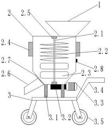
[0026] Such as figure 1 As shown, a new type of concrete mixer includes a hopper 1, a mixing drum 2 and a car body 3, the lower end of the hopper 1 is connected to the mixing drum 2, and the hopper 1 and the mixing drum 2 are welded; the mixing drum 2. A feeding port 2.6 is provided below, and a corresponding sealing cover 2.7 is provided at the feeding port 2.6; a vertical stirring shaft 2.1 is provided inside the mixing drum 2, and corresponding sealing covers are provided at both ends of the stirring shaft 2.1. Bearing 2.5 with a seat, a helical stirring blade 2.2 is arranged above the stirring shaft 2.1, and 4 sheet-like stirring blades 2.3 are arranged below, and the sheet-like stirring blade 2.3 and the stirring shaft 2.1 are welded; the stirring drum A shaft coupling 3.2 and a driving motor 3.3 are arranged below 1; the stirring shaft 2.1 is connected to the driving motor 3.3 through a coupling 3.2, and the stirring shaft 2.1, coupling 3.2 and driving motor 3.3 are all ...

Embodiment 2

[0031] Such as figure 1 As shown, a new type of concrete mixer includes a hopper 1, a mixing drum 2 and a car body 3, the lower end of the hopper 1 is connected to the mixing drum 2, and the hopper 1 and the mixing drum 2 are welded; the mixing drum 2. A feeding port 2.6 is provided below, and a corresponding sealing cover 2.7 is provided at the feeding port 2.6; a vertical stirring shaft 2.1 is provided inside the mixing drum 2, and corresponding sealing covers are provided at both ends of the stirring shaft 2.1. Bearing 2.5 with a seat, a spiral stirring blade 2.2 is arranged above the stirring shaft 2.1, and 6 sheet-like stirring blades 2.3 are arranged below, and the sheet-like stirring blade 2.3 is detachably connected to the stirring shaft 2.1; A shaft coupling 3.2 and a driving motor 3.3 are arranged below the mixing drum 1; the stirring shaft 2.1 is connected with the driving motor 3.3 through the shaft coupling 3.2, and the stirring shaft 2.1, the shaft coupling 3.2 a...


PUM


Abstract

The invention relates to the technical field of building equipment, and concretely relates to a novel concrete mixer, which comprises a loading hopper, a mixing drum and a trolley body, and is characterized in that the lower end of the loading hopper is interconnected with the mixing drum; a discharge outlet is formed in the lower part the mixing drum; a perpendicular mixing shaft is arranged in the mixing drum; a spiral mixing blade is arranged on the upper part the mixing shaft, and a plurality of flaky mixing blades are arranged on the lower part of the mixing shaft; a coupler and a drive motor are arranged under the mixing drum; the mixing shaft is connected with the drive motor through the coupler; the mixing drum is located above the trolley body; gravity sensing devices are arranged between the mixing drum and the trolley body; and vibrators are arranged on two sides of the mixing drum. The invention provides the novel concrete mixer which is convenient to operate, the usage amount of concrete can be controlled, materials are saved, and the mixing quality of the concrete is ensured.

Description

technical field [0001] The invention relates to the technical field of construction equipment, in particular to a novel concrete mixer. Background technique [0002] Most of the new concrete mixers currently on the market are large in size and heavy in weight. In order to ensure their stability during work, they are usually fixed on the ground at the construction site. The speed is fast, but its disadvantage is that it is inconvenient to move and the overall cost is high, so it is only suitable for large construction sites. In order to solve the shortage of large-scale new concrete mixers, the industry has designed and produced a series of small new concrete mixers. During the actual production and application, it was found that the service life of the mixing shafts of this type of small new concrete mixers is too short and easy to break; When the dust rises, it will affect the health of the builders after being inhaled; although it can be moved, it still needs to be fixed ...

Claims


Application Information

Patent Timeline
IPC IPC(8): B28C5/16B28C5/08B28C5/48
CPCB28C5/16B28C5/0806B28C5/0818B28C5/48
Inventor 唐浩城唐健发
Owner 唐健发
Why Eureka
Try Eureka