Bicycle speed change system and speed change method for power-assisted bicycle comprising same

A bicycle and vehicle speed technology, which is applied in the field of bicycle speed change system and power-assisted bicycle speed change, can solve the problems of high price, narrow speed change range, and inability to achieve many levels of speed changes, so as to save costs, improve cruising range, and expand high speed. Efficiency Operating Area and Effect of Output Torque Range

Inactive Publication Date: 2017-05-10
SUZHOU WANJIA ELECTRIC
View PDF13 Cites 4 Cited by
  • Summary
  • Abstract
  • Description
  • Claims
  • Application Information

AI Technical Summary

Problems solved by technology

However, the external transmission systems currently on the market, whether they are hub-type internal transmissions or external flywheel systems, are expensive, complicated to install and debug, and need to be adjusted by the riders themselves according to different road conditions. Rarely know how to adjust the transmission system, usually ride in one gear all the time, it is difficult to achieve the purpose of speed ch

Method used


Image

  • Bicycle speed change system and speed change method for power-assisted bicycle comprising same
  • Bicycle speed change system and speed change method for power-assisted bicycle comprising same
  • Bicycle speed change system and speed change method for power-assisted bicycle comprising same

Examples


Embodiment 1

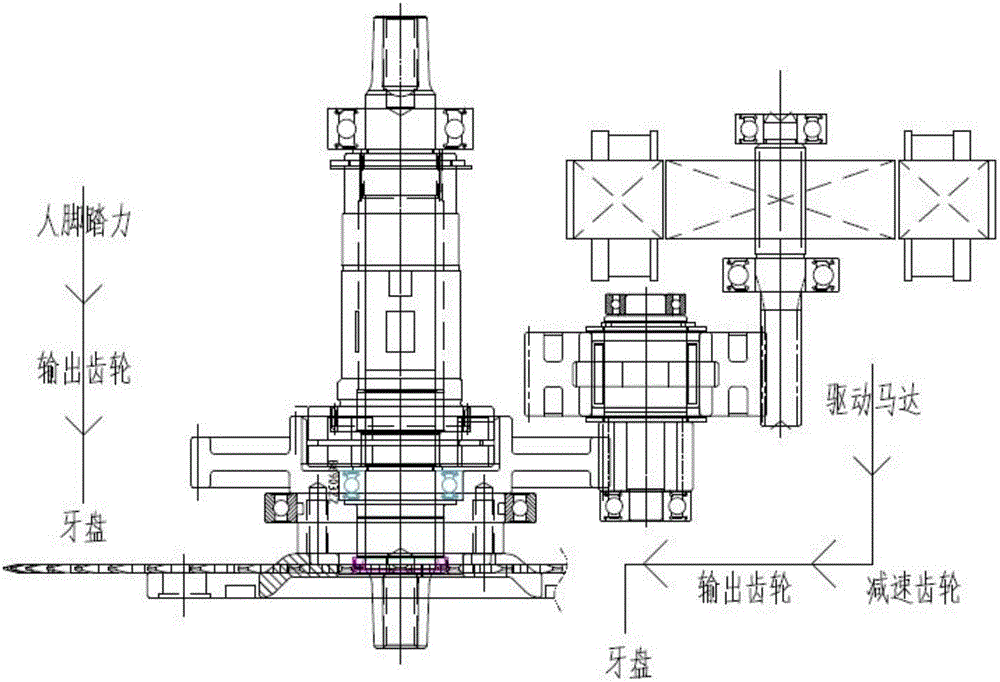
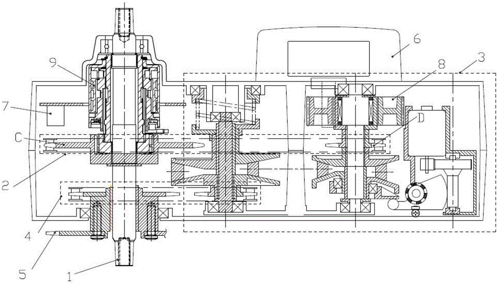
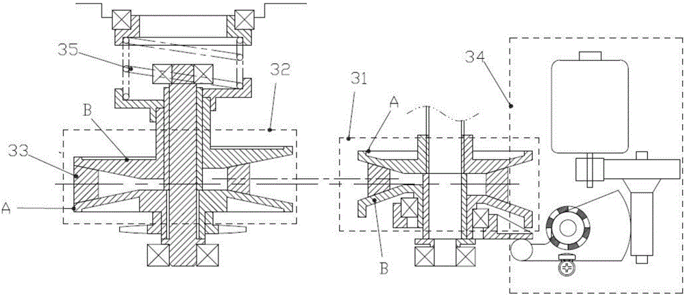
[0057] Please also see figure 2 , image 3 , as shown in the figure, a speed change system for a bicycle includes a drive mechanism and a speed change mechanism located at the output end of the drive mechanism. The speed change mechanism outputs the rotational speed to the bicycle crankset. Wherein the transmission mechanism is a continuously variable transmission mechanism 3, and the continuously variable transmission mechanism includes at least one group of transmission components, and each group of transmission components includes a driving cone wheel group 31, a driven cone wheel group 32, and is connected to the driving cone wheel group and the driven cone wheel group. The transmission belt 33 and the speed regulating assembly 34 on the driven cone wheel group, the driving cone wheel group 31 and the driven cone wheel group 32 all include two oppositely arranged cone wheels, which are respectively the fixed cone wheel A and the moving cone wheel B. The speed assembly ac...

Embodiment 2

[0108] See Figure 5 , the rest are the same as in Embodiment 1, the difference is that the speed regulating assembly includes a centrifugal ball 346, and a retaining cover 347 is fixed on the rear side of the movable cone wheel. A centrifugal ball moving chamber 350 is formed between the cover and the rear side of the movable cone wheel, and the space size of the moving chamber gradually increases from both sides to the middle; The centrifugal ball is set towards the middle to increase the assist ratio.


PUM


Abstract

The invention discloses a bicycle speed change system. By integrating a stepless speed change mechanism into a central system of a power-assisted bicycle, the current riding state is judged by a controller according to sensor information, the speed reducing ratio of manpower and a motor to a rear wheel of the bicycle is automatically adjusted, and thus, the driving motor can operate nearby a rated operation point; an efficient operation area and a torque output range of the central system are broadened, the endurance mileage is prolonged, and the cost of a power-assisted bicycle system is reduced; the central system can automatically judge the whole bicycle operation state according to the bicycle speed, the human foot treading frequency, the foot treading force and the treading direction, and the current power assist rate is automatically adjusted; and operation is easier, more convenient and more humanized, and speed change gears do not need to be adjusted manually.

Description

technical field [0001] The invention belongs to the design field of power-assisted bicycle speed change mechanisms, and in particular relates to a speed change system for bicycles and a speed change method for power-assisted bicycles including the system. Background technique [0002] Power-assisted bicycles, also known as power-assisted electric bicycles, are a riding tool between bicycles and electric vehicles. They provide the kinetic energy needed for bicycles through electric power to assist manpower. The product of an environmentally friendly lifestyle. The central system is the core component of power-assisted bicycles. It integrates torque detection, controller modules, and motor drives to control the normal driving of the vehicle. At present, power-assisted bicycles are more popular in foreign markets, such as Germany, Japan and other developed countries. In my country, electric bicycles still occupy the main market, and most electric bicycles are driven by wheel h...

Claims


Application Information

Patent Timeline
IPC IPC(8): B62M9/08B62M6/45
CPCB62M6/45B62M9/08
Inventor 黄福明蔡华林黄俊宁黄俊燚
Owner SUZHOU WANJIA ELECTRIC
Why Eureka
Try Eureka