
A cantilever beam moving and locking device

A locking device and cantilever beam technology, applied in floating buildings and other directions, can solve problems such as hidden safety hazards, large pushing force, metal adhesion, etc., achieve compact structure, reduce load bearing index, avoid damage and jamming. Effect

Active Publication Date: 2019-08-23
中石化石油工程技术服务有限公司 +2
View PDF8 Cites 0 Cited by
  • Summary
  • Abstract
  • Description
  • Claims
  • Application Information

AI Technical Summary

Problems solved by technology

[0002] The offshore platform is the infrastructure for the exploration and development of offshore oil and gas resources. Each shift requires the cooperation of multiple ships, and the cost is high. Therefore, in general, multiple wells can be drilled or repaired at one time. Shifting; usually the cantilever beam moves more than 20 meters, and its own weight is more than 1,000 tons when moving. The variable load that needs to be added during the cantilever beam operation is also hundreds of tons or even thousands of tons. It needs to be locked after the position. Therefore, a large pushing force is required when moving. Metal adhesion or damage often occurs at the sliding joint, and even cannot be moved. It is difficult to effectively and reliably lock during operation, which not only affects the operation but also exists Security risks

Method used


Image

  • A cantilever beam moving and locking device
  • A cantilever beam moving and locking device
  • A cantilever beam moving and locking device

Examples


Embodiment Construction

[0022] Now in conjunction with the accompanying drawings of the description, the present invention will be further described:

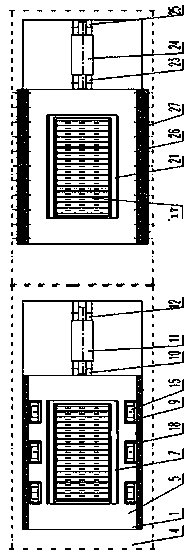
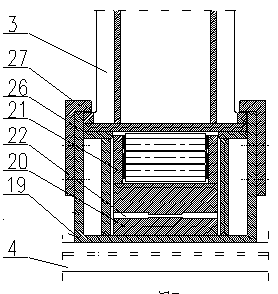
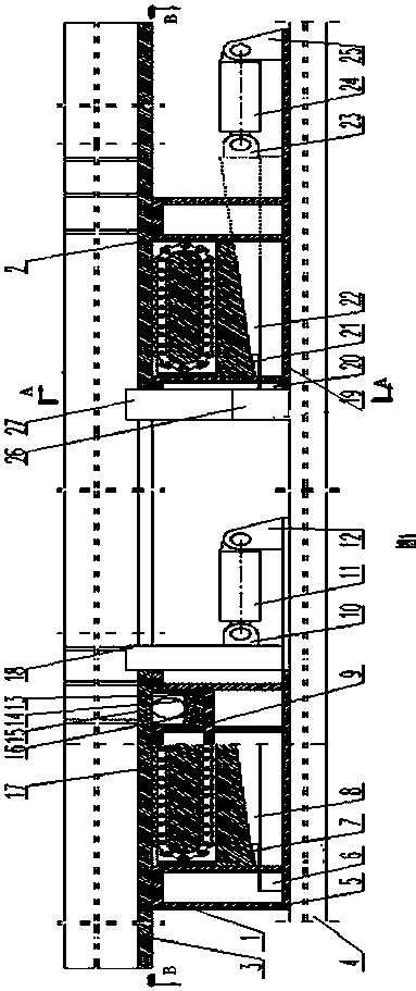
[0023] attached figure 1 with 2 , 3 provides a cantilever beam moving and locking device composed of two sets of cantilever beam moving mechanism monomers (also called monomers) and a set of locking mechanisms. The two sets of monomers have the same structure and are arranged on the platform body 4, the locking mechanism is fixedly connected to one side of the cantilever beam moving mechanism on the left side of the figure.

[0024] The left unit is composed of support I1, fixed seat I5, slide rail I6, upper wedge I7, lower wedge I8, earring I10, hydraulic cylinder I11, hydraulic cylinder bracket I12, roller carrier and roller I17, guide plate I18 . The right side unit consists of support II2, fixed seat II19, slide rail II20, upper wedge II21, lower wedge II22, earring II23, hydraulic cylinder II24, hydraulic cylinder bracket II25, roller carrier ...


PUM


Abstract

The invention relates to a moving and locking device for a cantilever beam, and belongs to the field of marine work platform auxiliary devices. The moving and locking device comprises a cantilever beam moving mechanism and a cantilever beam locking mechanism, and the cantilever beam moving mechanism is composed of one set of single bodies or formed by arraying multiple sets of single bodies at intervals in sequence; each set of single bodies comprises a supporting frame, a lifting mechanism arranged inside the supporting frame and a driving mechanism which is matched with the lifting mechanism in a driving mode; the locking mechanism comprises a locking block matched with the bottom surface of the cantilever beam in a locking mode, and is arranged on one side of each supporting frame. Moving and locking of the cantilever beam are combined in an integrated mode, by the adoption of a pin roller structure, force needed by movement can be greatly reduced, and meanwhile damage and blocking are avoided; by the adoption of a locking wheel locking mode, the weight of the facility to be moved is fully utilized, and the facility can be reliably locked at any position in a mechanical mode; the device has the advantages of being compact in structure, large in moving ability, reliable in locking, small in occupied space, good in economy and the like.

Description

technical field [0001] The invention relates to a cantilever beam moving and locking device in the field of auxiliary devices for offshore operation platforms, which is applied to the cantilever beam moving and locking at any position. Background technique [0002] The offshore platform is the infrastructure for the exploration and development of offshore oil and gas resources. Each shift requires the cooperation of multiple ships, and the cost is high. Therefore, in general, multiple wells can be drilled or repaired at one time. Shifting; usually the cantilever beam moves more than 20 meters, and its own weight is more than 1,000 tons when moving. The variable load that needs to be added during the cantilever beam operation is also hundreds of tons or even thousands of tons. It needs to be locked after the position. Therefore, a large pushing force is required when moving. Metal adhesion or damage often occurs at the sliding joint, and even cannot be moved. It is difficult ...

Claims


Application Information

Patent Timeline
Patent Type & Authority Patents(China)
IPC IPC(8): B63B35/44
Inventor 孙永泰蒙占彬崔希君尹慧敏杜大力董庆成李森于丽萍魏羲
Owner 中石化石油工程技术服务有限公司
Learn More