
Improved deep-water semi-submersible laying pipe floating crane

A semi-submersible and lifting vessel technology, applied in the direction of pipe-laying ships, hulls, hull decks, etc., can solve the problems of reducing the deck loading capacity in sailing conditions, the distance between the center of gravity and the center of buoyancy, and uneven thrust distribution. Achieve the effects of improving the variable load of the deck, facilitating equipment maintenance and purchasing

Inactive Publication Date: 2018-01-23
CHINA NAT OFFSHORE OIL CORP +1
View PDF5 Cites 3 Cited by
  • Summary
  • Abstract
  • Description
  • Claims
  • Application Information

AI Technical Summary

Problems solved by technology

[0003] The existing semi-submersible crane pipe-laying ships all arrange the living building at the bow, the main crane at the stern, and the center of gravity of the whole ship is at the rear. However, the stern of the lower floating body is usually The narrower design results in a longer distance between the center of gravity and the center of buoyancy under sailing conditions, and more ballast water is required for trimming, thus reducing the deck loading capacity under sailing conditions
In addition, due to the limited space of existing ship types, various types of propellers are usually arranged, which will cause problems such as uneven thrust distribution and complicated operation and maintenance.

Method used


Image

  • Improved deep-water semi-submersible laying pipe floating crane
  • Improved deep-water semi-submersible laying pipe floating crane
  • Improved deep-water semi-submersible laying pipe floating crane

Examples


Embodiment Construction

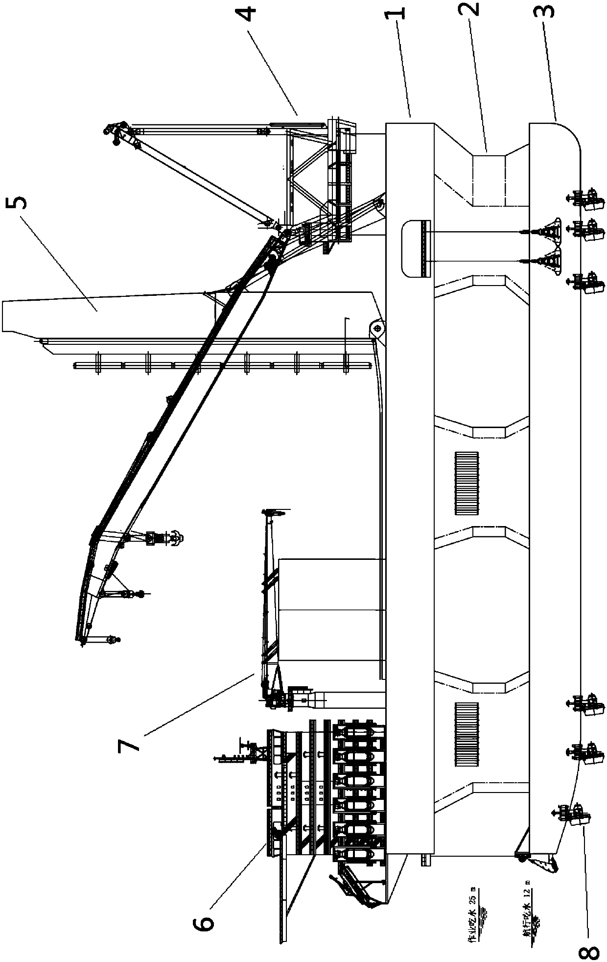
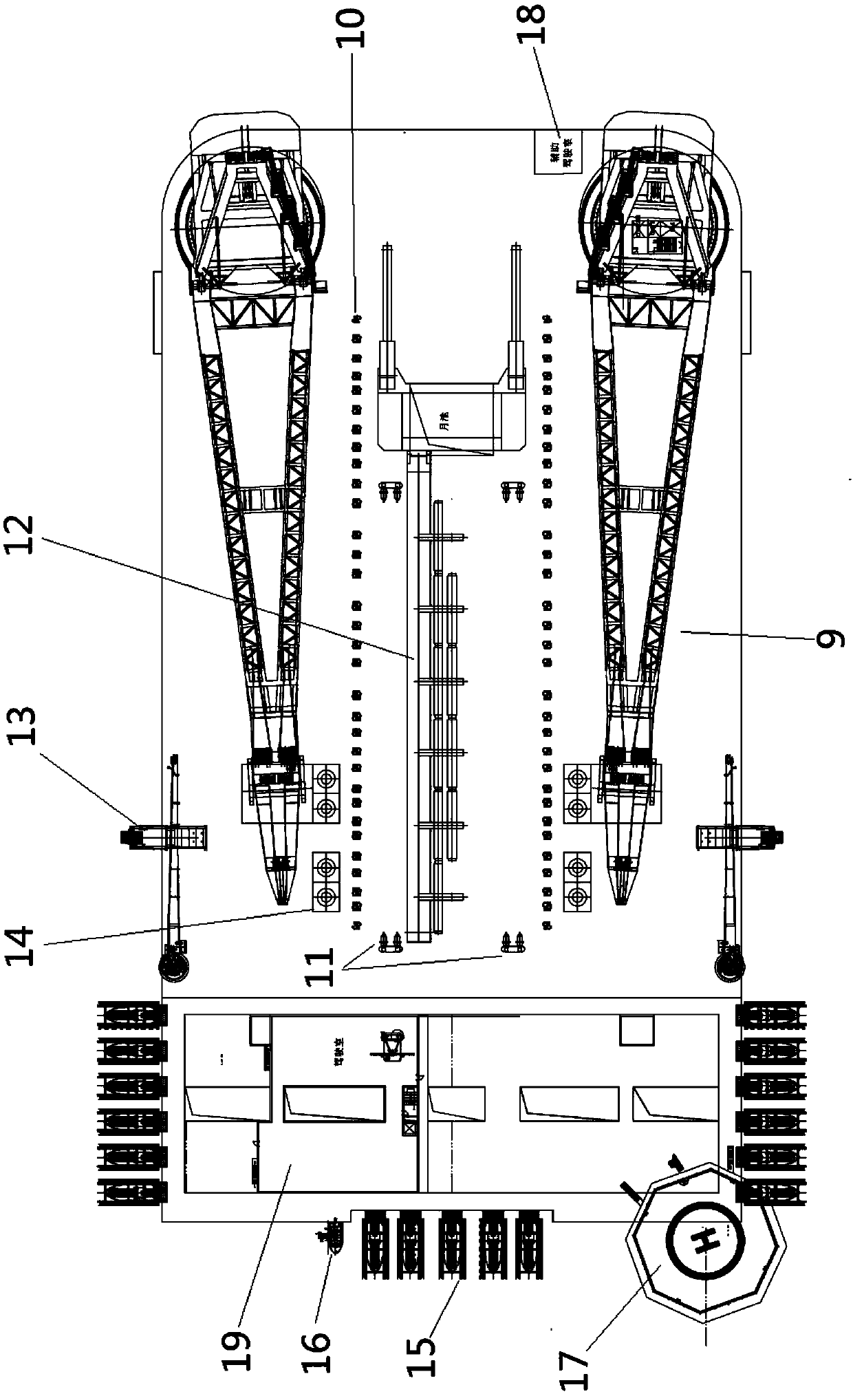
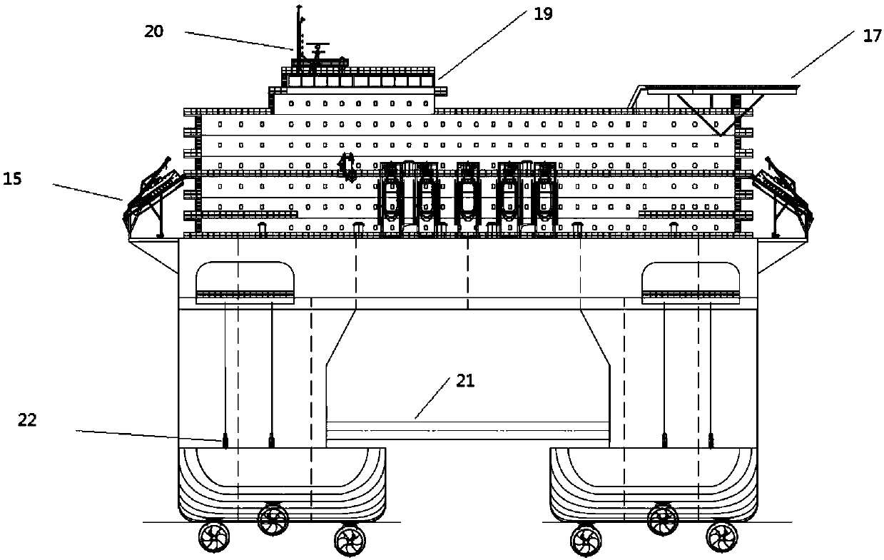
[0016] Such as Figure 1 to Figure 4 As shown, the improved deep-water semi-submersible pipe-laying crane ship of the present invention includes a main hull, which is composed of an upper floating body 1, a lower floating body 3, and a lower floating body and an upper floating body. It is composed of several columns 2 between them; it is characterized in that two main cranes 4 are arranged on the bow main deck of the upper floating body, a living building 6 is arranged at the stern of the upper floating body 1, and a J-shaped pipe laying tower 5 is arranged on the upper floating body 1 Near the middle of the bow, and the auxiliary cab 18 is set on the main deck of the bow of the floating body 1 .

[0017] Such as Figure 1 to Figure 4 As shown, the improved deep-water semi-submersible pipe-laying crane ship of the present invention, wherein: two main cranes 4 are arranged on the bow main deck of the floating body 1, and pipe stacking areas are respectively arranged under the ...


PUM


Abstract

The invention provides an improved deep-water semi-submersible laying pipe floating crane. A main floating ship body is composed of an upper floating body, a lower floating body and a plurality of stand columns which are arranged between the lower floating body and the upper floating body; the floating crane is characterized in that two main cranes are arranged on a main deck of the fore body of the upper floating body, a living building is arranged on the stern portion of the upper floating body, a J-shaped laying pipe tower is arranged in the middle of the portion, close to the fore body, ofthe upper floating body, and an auxiliary cab is arranged in the middle of the fore body of the upper floating body; the variable load of a deck of the sailing working condition can be effectively improved; the lifting operation and the pipe laying operation do not intervene manually; when the sailing working condition of a ship is converted into the operation working condition, the position change of the buoyant center is small, the adjustment requirement of ballast water is relatively reduced, and accordingly load adjustment is conducted more conveniently; a same type is adopted for all thrusters, so that the floating crane is easy and convenient to operate; spare parts are purchased more conveniently, and the device is maintained more conveniently.

Description

technical field [0001] The invention relates to a pipe-laying crane ship, in particular to an improved deep-water semi-submersible crane-laying ship. Background technique [0002] In recent years, offshore oil development is moving towards farther, deeper and harsher deep-sea marine blocks. Traditional offshore engineering ships have a small operational weather window in sea areas, making it difficult to complete oil and gas field development tasks. The deep-water semi-submersible crane pipe-laying vessel can carry out various offshore engineering operations such as J-Lay sea pipe laying and hoisting of large structures under harsh deep-water environmental conditions. It is the top engineering equipment for deep-water oil and gas field development. At present, there are two ship types used in deepwater pipe-laying crane ships: conventional monohull ship and semi-submersible ship type. The semi-submersible crane-laying ship has better seakeeping performance due to its smalle...

Claims


Application Information

Patent Timeline
Patent Type & Authority Applications(China)
IPC IPC(8): B63B35/03B63B3/48B63B3/00
Inventor 钟文军何宁彭小佳张法富蔡元浪宋安科杨宁冯庆斌赵建宇方堃
Owner CHINA NAT OFFSHORE OIL CORP
Learn More