Tension force leg drill platform

A drilling platform and tension leg technology, which is applied in construction, artificial island, infrastructure engineering, etc., can solve the problems of large deepwater tension leg drilling platform, high construction cost and heavy weight.

Inactive Publication Date: 2009-08-19
中国船舶重工集团公司第七〇二研究所
View PDF0 Cites 6 Cited by
  • Summary
  • Abstract
  • Description
  • Claims
  • Application Information

AI Technical Summary

Problems solved by technology

If the column center distance is large, the area of ​​the superstructure will be large, not only the entire

Method used


Image

  • Tension force leg drill platform
  • Tension force leg drill platform

Examples


Embodiment Construction

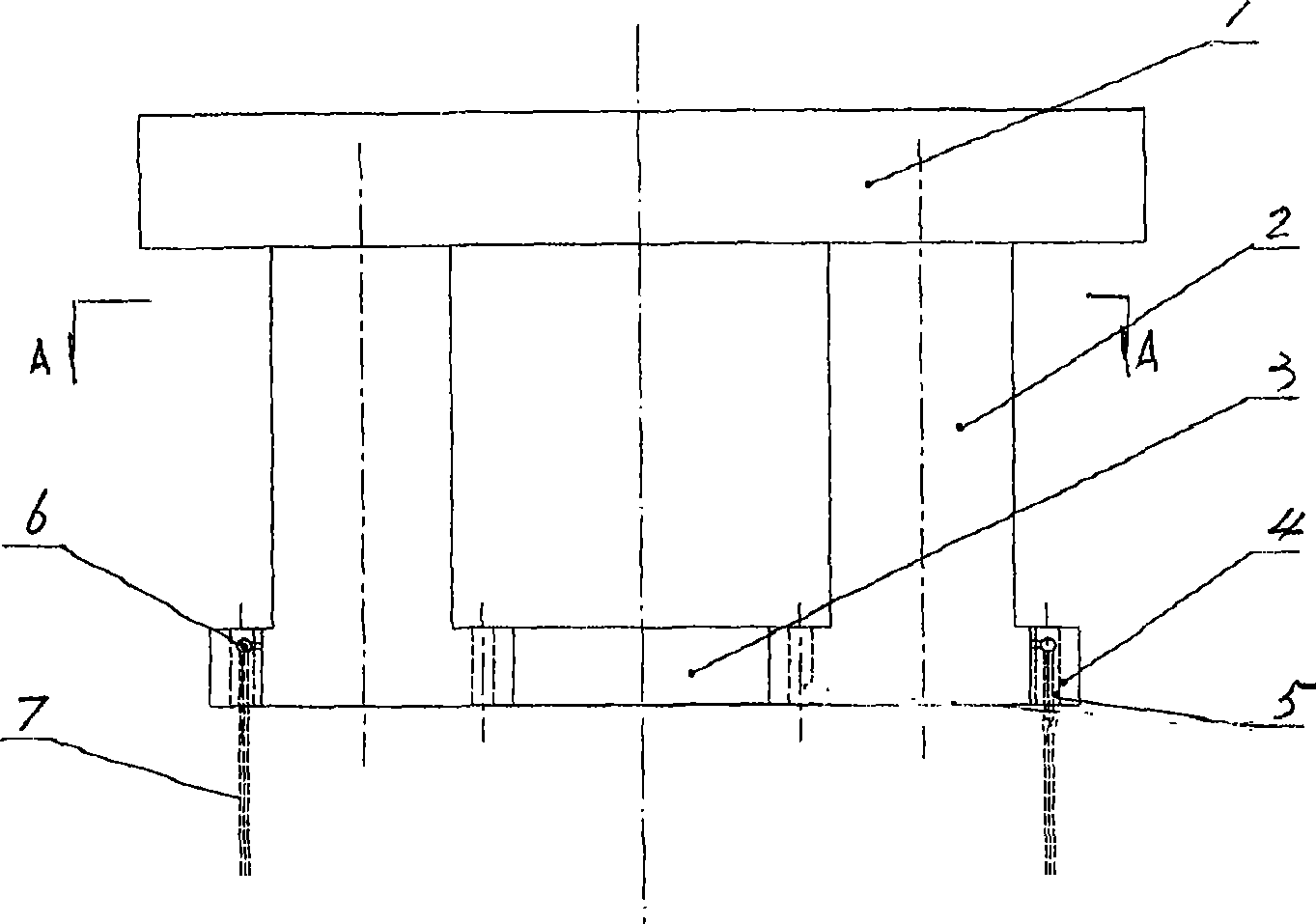
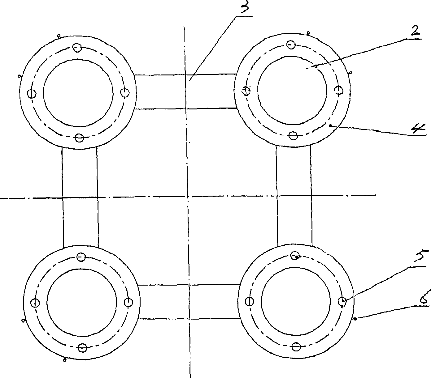
[0011] Such as figure 1 and figure 2 As shown, the tension leg drilling platform of the present invention includes a superstructure 1, and columns 2 are arranged at four corners of the superstructure 1 below. The columns 2 are cylindrical and perpendicular to the upper and lower sides of the superstructure 1 , and their upper ends are respectively fixed to the four corners of the superstructure 1 . A rectangular cross-section caisson 3 is arranged between the lower ends of two adjacent columns 2, and a disc-shaped caisson 4 is arranged between the lower end of each column 2 and the rectangular-section caissons 3 on both sides. It is connected with the rectangular section caisson 3. The outer side of each column 2 is provided with a tension tendon 7, and the upper and lower ends of the tension tendon 7 are respectively fixedly connected with the outer side of the lower end of the column 2 and the seabed base. Wherein, the upper end of each tension tendon 7 is anchored on th...


PUM


Abstract

The invention relates to a tension leg drilling platform, in particular to a deepwater tension leg drilling platform used for carrying out deepwater petroleum extraction. The deepwater tension leg drilling platform comprises a superstructure, and four corners under the superstructure are all provided with upright posts. The upright posts are vertical to the top surface and the bottom surface of the superstructure, and the upper ends are connected with the superstructure fixedly. The lower ends of two adjacent upright posts are all provided with rectangular section caissons. The outer side of each upright post is all provided with a tension tendon. The upper end and the lower end of the tension tendon are respectively connected with the outer side of the lower end of the upright post and a benthal pedestal. The deepwater tension leg drilling platform is characterized in that a disc type caisson is arranged between the lower end of each upright post and the rectangular section caissons at two sides of the upright post; and all disc type caissons are connected with the upright post and the rectangular section caissons. The tension leg drilling platform has large load, low self gravity and low construction cost.

Description

technical field [0001] The invention relates to an offshore operation platform. Specifically, it is a deepwater tension leg drilling platform used for deepwater oil extraction. Background technique [0002] At present, the drilling platforms used for deepwater oil exploitation are traditional deepwater tension leg drilling platforms. This drilling platform contains a superstructure with columns at the four corners below the superstructure. The column is perpendicular to the upper and lower sides of the superstructure, and its upper end is fixedly connected to the superstructure. There is a caisson with a rectangular section between the lower ends of two adjacent columns, and the column is connected to the caisson. There are tension tendons on the outer side of each column, and the upper and lower ends of the tension tendons are respectively connected with the outer side of the lower end of the column and the seabed base. Since there is only a caisson with a rectangular se...

Claims


Application Information

Patent Timeline
IPC IPC(8): E02B17/00
Inventor 缪泉明匡晓峰杨烁李忠刚
Owner 中国船舶重工集团公司第七〇二研究所
Why Eureka
Try Eureka