Supercharge Your Innovation With Domain-Expert AI Agents!

Pulling device applied to pipe turnover plate frame

A technology of traction device and turning plate, which is applied in the direction of transportation and packaging, conveyors, rollers, etc., can solve the problems of unfavorable production line production efficiency, plastic material wear, single function, etc., and achieve the effect of improving practicability and stable migration

Inactive Publication Date: 2017-05-10
ANHUI JIELANTE NEW MATERIAL CO LTD
View PDF17 Cites 1 Cited by
  • Summary
  • Abstract
  • Description
  • Claims
  • Application Information

AI Technical Summary

Problems solved by technology

In traditional production, manual unloading is generally used. Usually, most pipe products have high technical requirements in terms of specifications and length, and the length and weight of pipes are relatively large. At this time, manual unloading not only has high labor intensity. , easy to wear and other technical problems during transmission, and it is not conducive to the improvement of the production efficiency of the production line
[0003] At the same time, during the manual operation of the pipe transmission process, the surface of the plastic pipe is prone to wear due to friction, impact, etc., which affects sales and brings unnecessary economic loss to the manufacturer.
[0004] The existing pipe turnover racks on the market all have a single function, and most of them are only used for support turnover in the processing of pipes of a single specification, and cannot have the function of automatic longitudinal transmission. The present invention aims to develop a The traction device of the turning frame, on the basis of the original turning frame, introduces the mechanism design of the pipe conveying device, realizes the direct and precise traction and transmission of the pipe on the turning frame, and realizes the automation of pipe production, transportation and processing; When the pipe products need to be transferred to the next processing section on the support frame, automatic transfer is realized without manual handling, which improves production efficiency
[0005] This case studies and designs a traction device applied to the pipe turning frame, aiming at solving the problem that the existing pipe supporting turning frame device cannot achieve automatic transportation and processing of pipes due to its simple structure and single function, and at the same time improves the pipe production process. detection processing efficiency

Method used


Image

  • Pulling device applied to pipe turnover plate frame
  • Pulling device applied to pipe turnover plate frame
  • Pulling device applied to pipe turnover plate frame

Examples


Embodiment Construction

[0023] In order to make the object, technical solution and advantages of the present invention clearer, the present invention will be further described in detail below in conjunction with the accompanying drawings and embodiments. It should be understood that the specific embodiments described here are only used to explain the present invention, not to limit the present invention.

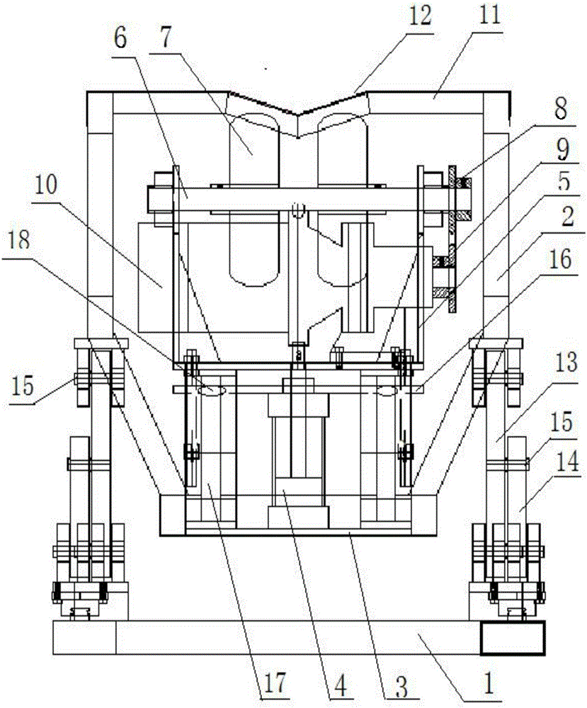
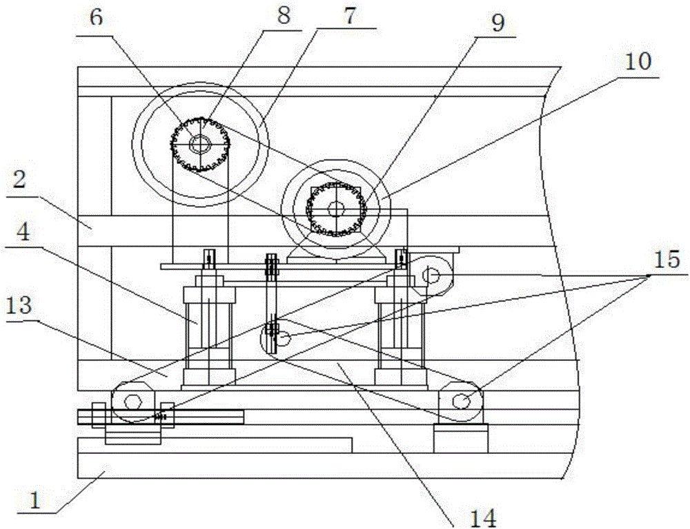
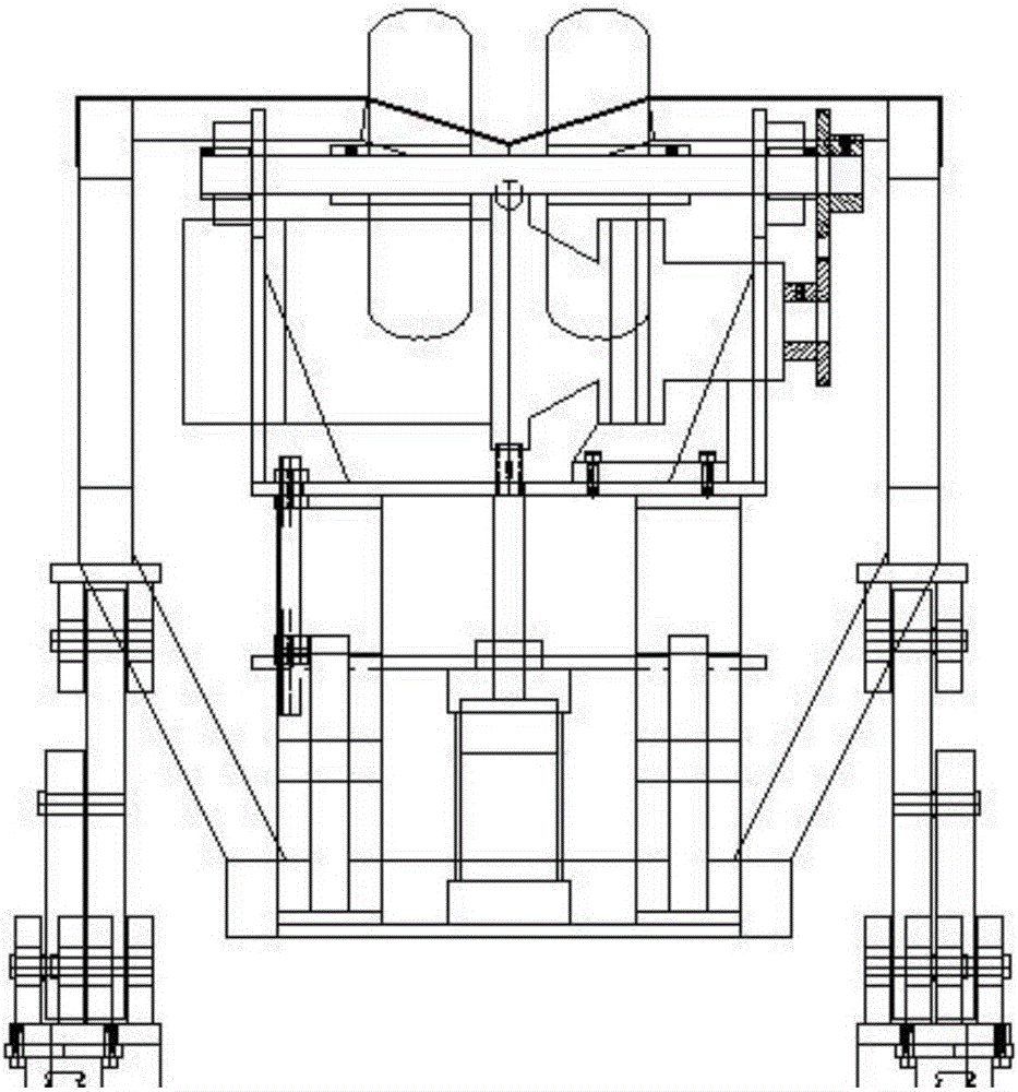
[0024] Such as Figure 1-3 As shown, the present invention provides a traction device applied to a pipe turnover frame, which includes a support frame, and is characterized in that: the support frame includes an upper frame 2 and an underframe 1, and the lower end of the upper frame 2 is provided with a base 3, and on the base 3 A hydraulic cylinder 4 is fixed, and the upper end surface of the hydraulic cylinder 4 is fixedly connected with a traction mechanism through an output shaft;

[0025] The traction mechanism includes a support bracket 5, and the upper position between the two side walls of...


PUM


Abstract

A pulling device for a pipe comprises a supporting frame. The supporting frame comprises an upper frame and a bottom frame. A base is arranged at the lower end of the upper frame. A hydraulic cylinder is fixedly arranged on the base. A pulling mechanism is connected to the upper end surface of the hydraulic cylinder through an output shaft and comprises a supporting bracket. A rotatable rolling wheel shaft is transversely arranged on the upper portions between the two side walls of the supporting bracket. A pair of rolling wheels are arranged in the positions, located in the middle of the supporting bracket, of the rolling wheel shaft in a sleeving mode. One end of the rolling wheel shaft is sleeved with a first linkage gear. A driving motor is transversely arranged on the supporting bracket. The output shaft is sleeved with a second linkage gear. The first linkage gear and the second linkage gear are linked through a transmission chain. The rolling wheels rotate and pull the pipe. The gap between the rolling wheels can be adjusted, the pulling device is matched with a stable V-shaped supporting platform structure, and stable automatic pulling is achieved; and the pulling device is matched with a height adjusting structure and combined with a turnover plate frame device, is stable in migration and can be suitable for functional improvement of various pipe product brackets and production lines.

Description

technical field [0001] The invention relates to the technical field of pipe production and processing equipment, and more specifically, to a traction device applied to a pipe turning frame. Background technique [0002] The pipe turning device is generally used at the end of the manufacturing line of various pipe products to complete the processing, cutting and unloading of pipe products. In traditional production, manual unloading is generally used. Usually, most pipe products have high technical requirements in terms of specifications and length, and the length and weight of pipes are relatively large. At this time, manual unloading not only has high labor intensity. , easy to wear and other technical problems during transmission, and it is not conducive to the improvement of the production efficiency of the production line. [0003] At the same time, during the manual operation of the pipe transfer process, the surface of the plastic pipe is prone to wear due to friction...

Claims


Application Information

Patent Timeline
Patent Type & Authority Applications(China)
IPC IPC(8): B65G13/07
CPCB65G13/07B65G2201/0276
Inventor 刘俊峰刘文江万刚
Owner ANHUI JIELANTE NEW MATERIAL CO LTD
Features
  • R&D
  • Intellectual Property
  • Life Sciences
  • Materials
  • Tech Scout
  • Unparalleled Data Quality
  • Higher Quality Content
  • 60% Fewer Hallucinations
Learn More