rope grip

A rope gripper and gripper block technology is applied in the field of rope grippers, which can solve the problems of reduced action sensitivity and reliability of the rope gripper, and achieve the effects of improving movement flexibility, reducing friction coefficient and reducing resistance.

Active Publication Date: 2019-05-21
SHIJIAZHUANG WULON BRAKE
View PDF6 Cites 0 Cited by
  • Summary
  • Abstract
  • Description
  • Claims
  • Application Information

AI Technical Summary

Problems solved by technology

[0004] The object of the present invention is to provide a rope gripper to solve the problem that the action sensitivity and reliability of the rope gripper are reduced due to the use of a large tension spring to locate the movable gripper.

Method used


Image

  • rope grip
  • rope grip
  • rope grip

Examples


Embodiment Construction

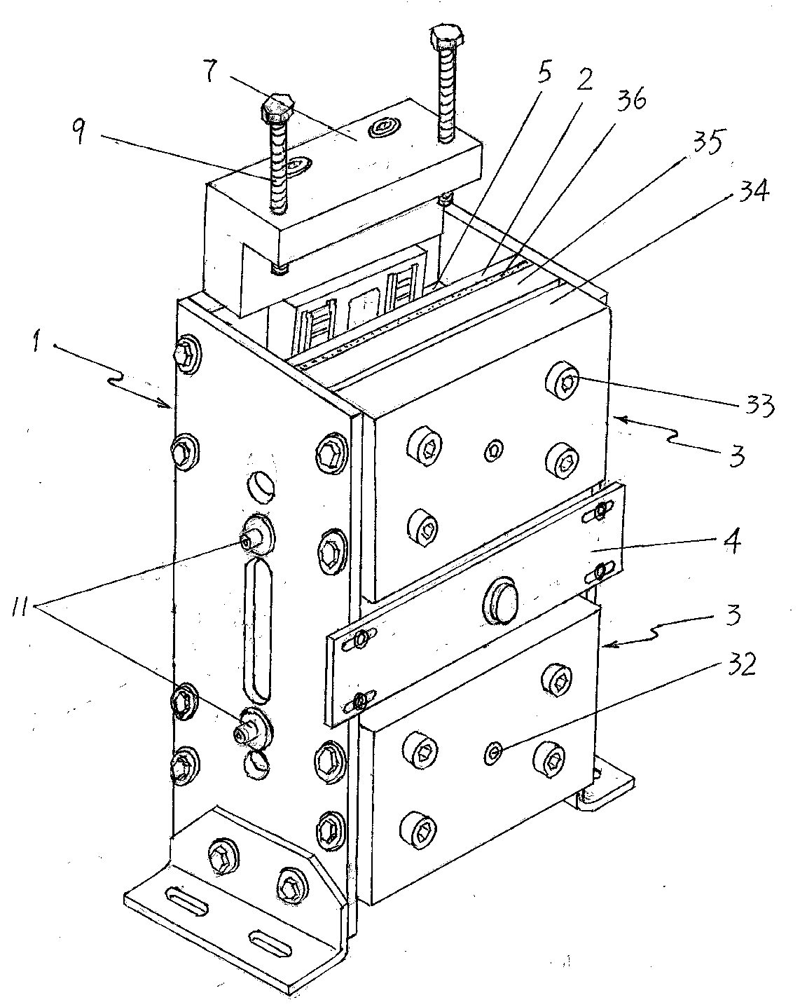
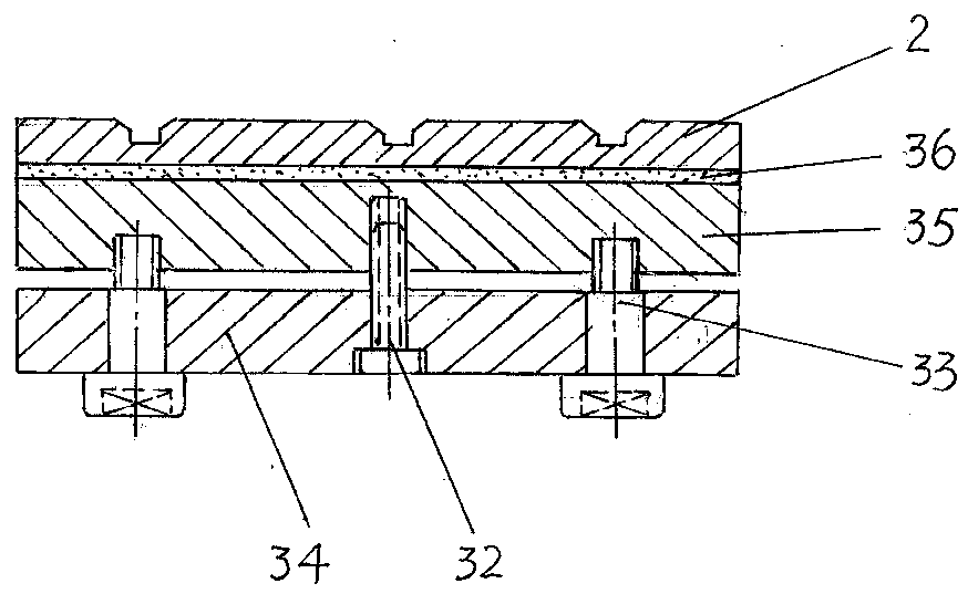
[0025] Such as figure 1 As shown, the rope gripper of the present invention includes a frame 1, two fixed clamping blocks 3 fixed on the frame, and a movable clamping block 5 opposite to the fixed clamping blocks and arranged in the center. Friction plates 2 ( Figure 4 , Figure 5 ); the longitudinal gap formed between the movable clamping block 5 and the fixed clamping block 3 is the rope passage for the traction wire rope to pass through.

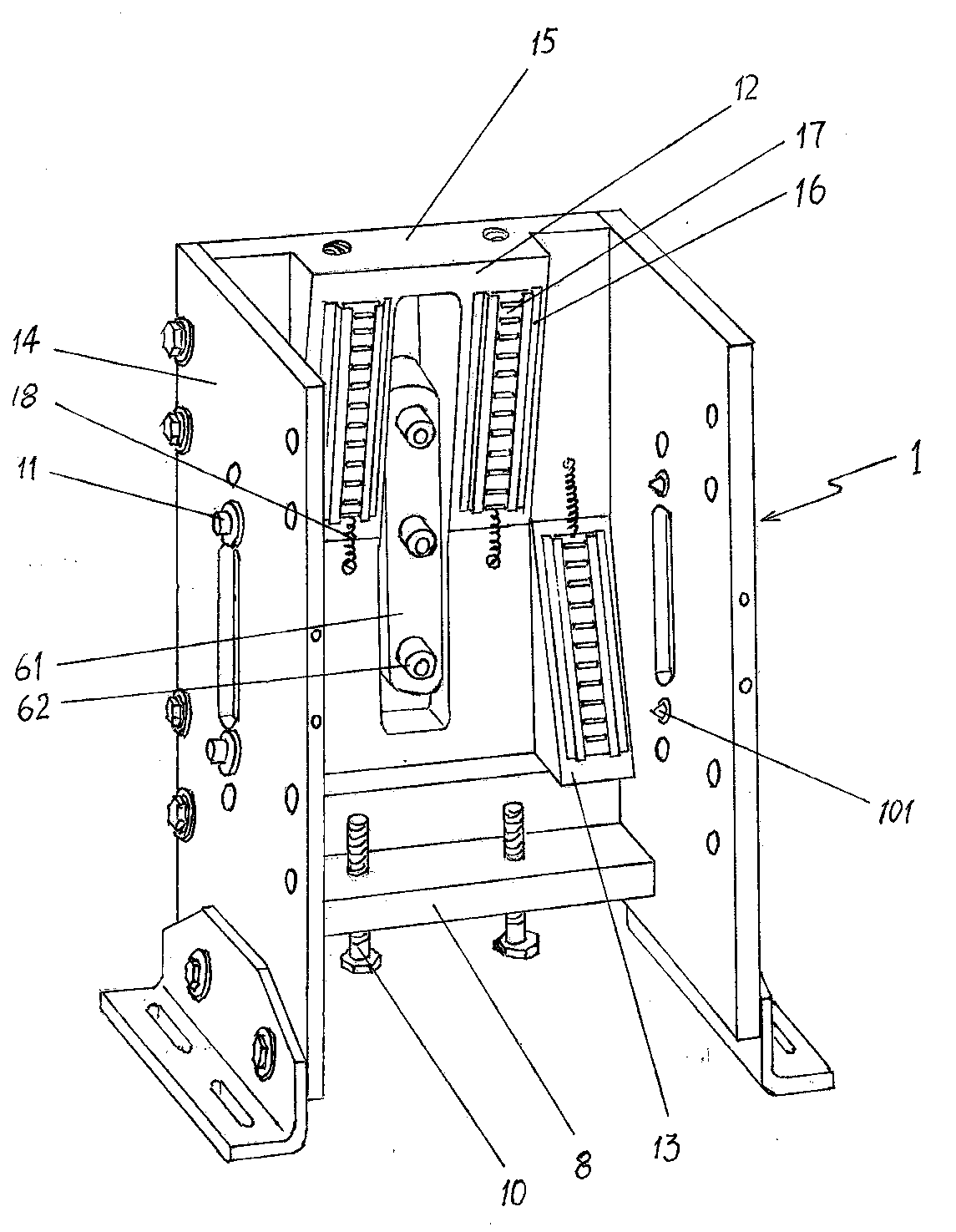
[0026] Such as figure 2 As shown, the frame 1 is a vertical trough-shaped body surrounded by two side plates 14 and a rear end plate 15 located between the two side plates, and an upper wedge-shaped upper part of the inner wall of the rear end plate 15 is centered. The upward stop surface 12 is symmetrically provided with two downward wedge-shaped downward stop surfaces 13 on both sides of the lower inner wall of the rear end plate 15, and the inner edge of the downward stop surface 13 is closely adjacent to the outer edge of the upw...


PUM


Abstract

The invention relates to a rope gripper. The structure of the rope gripper comprises a frame, a fixed clamp block and a moveable clamp block, wherein first spring plungers are arranged on the frame; an uplink stopping surface and a downlink stopping surface are arranged on a rear end plate of the frame; a rear pushing mechanism and a front pushing mechanism are arranged on the frame; the rear pushing mechanism is used for pushing a rear wall of the moveable clamp block; the front pushing mechanism is used for pushing a front end face of the moveable clamp block; an uplink slide rail, a downlink slide rail and a vertical surface slide rail are arranged on the rear side of the moveable clamp block; the vertical surface slide rail is opposite to the rear pushing mechanism arranged on the frame; clamping cross slots are respectively formed on the two sides of the moveable clamp block; the front ends of the plunger bodies of the first spring plungers are clamped in the clamping cross slots. According to the invention, the action sensitivity and the working reliability of the rope gripper can be increased; the safe braking performance of a safety brake is promoted; the gravity deceleration of the rope gripper under an emergency braking condition can be regulated, so that the standard requirement of an emergency braking specification for the safety brake can be met; the situation that people in an elevator are hurt by the emergency braking can be effectively avoided.

Description

technical field [0001] The invention relates to a safety brake, in particular to a rope clamp. Background technique [0002] In order to prevent vicious casualty accidents caused by unexpected movement of the car, improve the safety of elevator use, and meet the safety standard requirements for elevator installation and use, the applicant proposed a new design of a wedge-shaped rope clamp that can be used as an elevator safety brake. The structure of this wedge-shaped rope clamp is that two brake clips with opposite clamping surfaces are arranged in the frame, and a rope channel is formed between the clamping surfaces of the two brake clamps. Among the two brake clamps, There is at least one movable clamping block that can move up and down in the frame. The movable clamp block is a wedge-shaped block, and the inner edge of the frame fitted with the wedge-shaped surface of the movable clamp block is a wedge-shaped inner groove surface, and the movable clamp block is attached...

Claims


Application Information

Patent Timeline
Patent Type & Authority Patents(China)
IPC IPC(8): B66B5/18
CPCB66B5/18
Inventor 韩伍林郝雄毅
Owner SHIJIAZHUANG WULON BRAKE
Why Eureka
Try Eureka