Flushing valve provided with connecting rod type transmission mechanism

A technology of transmission mechanism and flush valve, applied in the field of sanitary ware, can solve the problems such as the limitation of lifting position, and achieve the effect of reducing the torsional moment and reducing the opening force value.

Pending Publication Date: 2017-05-10
XIAMEN R&T PLUMBING TECH
View PDF0 Cites 1 Cited by
  • Summary
  • Abstract
  • Description
  • Claims
  • Application Information

AI Technical Summary

Problems solved by technology

[0003] In the above-mentioned prior art, the link-type transmission mechanism composed of the pressing rod 41' and the connecting rod 42' is only pivotally connected to the valve body through a pivot joint. This structure ensures smoother lifting of the lifting pipe 3' Under the premise, it is difficult to flexibly select the lifting position of the riser 3' according to the needs, and the lifting position is limited

Method used


Image

  • Flushing valve provided with connecting rod type transmission mechanism
  • Flushing valve provided with connecting rod type transmission mechanism
  • Flushing valve provided with connecting rod type transmission mechanism

Examples


no. 1 example

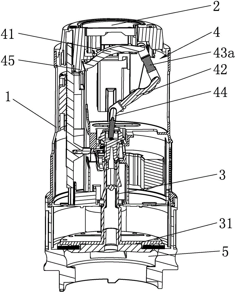
[0033] Such as Figure 2 to Figure 4 , Figure 2 to Figure 4 A flush valve with a link-type transmission mechanism according to the first embodiment of the present invention is shown, which includes a valve body 1, an actuating element 2, a riser pipe 3 and a transmission mechanism 4, and the actuating element 2 and the riser pipe 3 are movable In the valve body 1, the starting element 2 of this embodiment is a button, and the button is movably installed in the button seat provided on the top of the valve body 1. Cooperating with the valve disc 31, the actuating element 2 lifts the lift pipe 3 upwards through the transmission mechanism 4 and then drives the valve disc 31 to move upwards to open the drain port 5 of the flush valve to realize drainage. The transmission mechanism 4 at least includes a connecting rod I41 and a connecting rod II42. The connecting rod I41 is in transmission cooperation with the starting element 2. The connecting rod II42 is used to lift the riser 3...

no. 2 example

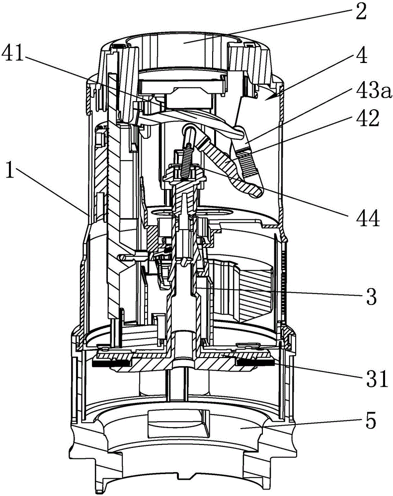
[0042] Such as Figure 5-7 As shown, this embodiment is a simple transformation of the first embodiment, and its difference from the first embodiment is only that: the second end of the push rod 43a of this embodiment slides with the first end of the connecting rod II 42 and Rotation fit, specifically, a chute 411 is provided on the second end of the push rod 43a, the rotating shaft 421 provided at the first end of the connecting rod II 42 extends into the chute 411 and slides and rotates in the chute 411, and the rest of the structure is the same as The first embodiment is the same.

[0043] When draining work, such as Figure 6 and Figure 7 As shown, press the activation element 2, the activation element 2 presses down the connecting rod I41, the connecting rod I41 rotates around its first pivotal part 45 and pushes the push rod 43a, and the push rod 43a pushes down the first end of the connecting rod II42 , so that the first end of the connecting rod II 42 moves from on...

no. 3 example

[0046] Such as Figure 8-10 As shown, this embodiment is a simple transformation of the first embodiment, and its difference from the first embodiment is that this embodiment is not provided with a push rod 43a, specifically, the first end of the connecting rod I41 is pivotally connected to A first pivot joint 45 is formed on the valve body 1, the second end of the connecting rod I41 rotates and slides with the first end of the connecting rod II42, and a slide groove 411 can be optionally provided on the second end of the connecting rod I41, so that The rotating shaft 421 provided on the first end of the connecting rod II 42 extends into the chute 411 and rotates and slides in the chute 411 at the same time, or, in reverse, the first end of the connecting rod II 42 is provided with a chute , so that the rotating shaft provided on the second end of the connecting rod I41 extends into the chute and rotates and slides in the chute at the same time, which realizes the rotation of ...


PUM


Abstract

The invention discloses a flushing valve provided with a connecting rod type transmission mechanism. The flushing valve comprises a starting element movably installed in a valve body and a lifting pipe, wherein a valve disc matched with a water draining port of the flushing valve is fixedly connected to the bottom end of the lifting pipe. The flushing valve further comprises the transmission mechanism, wherein the transmission mechanism comprises, at least, a connecting rod I matched with the starting element in a transmission mode and a connecting rod II for lifting the lifting pipe, the connecting rod I is matched with the connecting rod II in a transmission mode, at least two supporting portions are arranged between the transmission mechanism and the valve body, and accordingly the lift-pulling position of the lifting pipe is flexibly selected as required on the premise that smooth lifting of the lifting pipe is ensured. On one hand, space layout of the transmission mechanism in the valve body is facilitated; on the other hand, the lift-pulling position of the transmission mechanism to the lifting pipe can be close to the lifting pipe or is directly arranged on the lifting pipe, accordingly a torsional moment of the transmission mechanism when the lifting pipe is lifted is greatly decreased or even zero, further a turning-on force value of the flushing valve is decreased, and a force saving effect is achieved.

Description

technical field [0001] The invention relates to the bathroom field, in particular to a flush valve with a link-type transmission mechanism. Background technique [0002] The transmission mechanism of the existing flush valve generally includes a button, a pressing rod 41', a connecting rod 42', a lifting arm 34', and a lifting pipe 3', such as figure 1 As shown, press the button, press the button to press down one end of the pressure rod 41', the other end of the pressure rod 41' lifts up and pulls the connecting rod 42' to move upward, and the connecting rod 42' pulls the lifting tube through the horizontally arranged lifting arm 34' 3' move upward together, the riser pipe 3' guides and cooperates with the valve body 1' and drives the valve disc 31' to move up to open the drain port of the flush valve to realize the drainage process. [0003] In the above-mentioned prior art, the link-type transmission mechanism composed of the pressing rod 41' and the connecting rod 42' i...

Claims


Application Information

Patent Timeline
Patent Type & Authority Applications(China)
IPC IPC(8): E03D5/09
CPCE03D5/09
Inventor 蒋友平周洪文王志忠王兴东
Owner XIAMEN R&T PLUMBING TECH
Why Eureka
Try Eureka