Infrared temperature measurement and variable emittance based laser welding safety control method and system

A technology of laser welding and infrared temperature measurement, which is applied in welding equipment, manufacturing tools, electric heating devices, etc.

Active Publication Date: 2018-07-24
WUHAN LINGYUN PHOTOELECTRONICS SYST
View PDF9 Cites 12 Cited by
  • Summary
  • Abstract
  • Description
  • Claims
  • Application Information

AI Technical Summary

Problems solved by technology

But this traditional method has the following serious shortcomings: non-contact temperature measurement must use infrared temperature sensor, the principle is that in nature, when the temperature of an object is higher than absolute zero, due to the existence of its internal thermal motion, it will continue to Radiate electromagnetic waves to the surroundings, including infrared rays with a band of 0.75 to 100 μm. The infrared temperature sensor uses this principle
Due to the above-mentioned defects, the laser constant temperature welding system is rarely used in actual engineering applications and mostly stays in the experimental research and demonstration stage

Method used


Image

  • Infrared temperature measurement and variable emittance based laser welding safety control method and system
  • Infrared temperature measurement and variable emittance based laser welding safety control method and system
  • Infrared temperature measurement and variable emittance based laser welding safety control method and system

Examples


Embodiment Construction

[0041] The system and method of the present invention are described below in conjunction with the accompanying drawings, and the examples given are only used to explain the technical solution of the present invention, and are not used to limit the protection scope of the present invention.

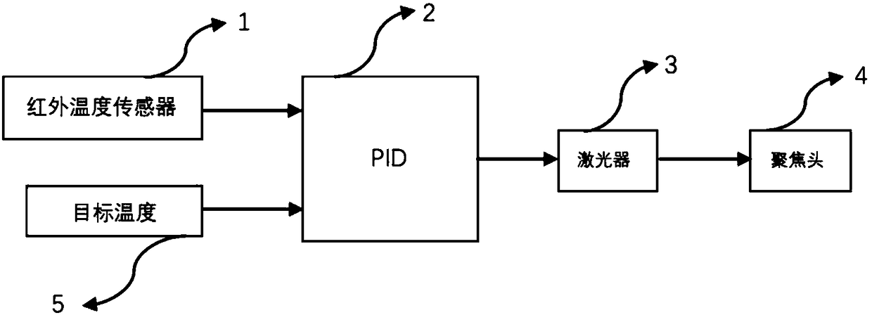
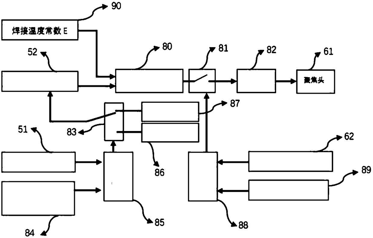
[0042] Such as figure 2 As shown, the technical solution system of the present invention includes

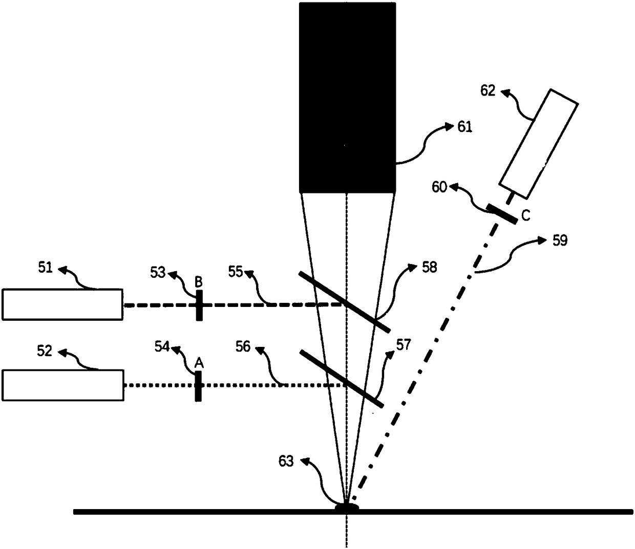
[0043] The optical paths of the three detection units are, respectively,

[0044] The infrared temperature detection optical path (infrared temperature detection at the laser welding point) includes a reflector A 57 , an optical filter A 54 and an infrared temperature sensor 52 arranged in sequence along the optical path 56 .

[0045] The laser reflected light intensity detection optical path at the laser welding point includes a filter C60 and a reflected light laser sensor 51 arranged in sequence along the optical path 59 .

[0046] The optical path for detecting visible light when the ...


PUM


Abstract

The invention discloses an infrared temperature measurement and variable emittance based laser welding safety control method and system. The method is that the temperature of a welding point of a welded object is detected based on the infrared temperature during laser welding, thus controlling a laser to work based on the feedback result. The method is characterized in that the intensity of reflected light at the welding point of the welded object is detected and compared with the brazing emitting light intensity threshold so as to determine whether a brazing filler metal of the welding pointreaches a melting point; the corresponding emittance constant is selected for infrared temperature detection under different states. According to the method, the state of the welded point is analyzedand determined to realize variable emittance control of an infrared temperature sensor; different emittance is adopted for infrared temperature detection based on different state of the welding point.Therefore, the problem that the temperature of the welding point cannot be accurately detected in the prior art can be solved, and the working state of the laser can be controlled; the system is integrated, so that the space layout of the system is reasonably performed; the space for equipment is small; the state of the welding point can be accurately controlled; and moreover, the constant-temperature control in the laser welding process can be realized.

Description

technical field [0001] The invention belongs to the laser welding technology, in particular to a temperature detection safety control technology in the laser welding process. Background technique [0002] The main feature of laser soldering is to use the high energy density of the laser to achieve rapid heating of local or small areas to complete the brazing process. The key to laser brazing lies in the reasonable control of laser power distribution. The laser beam converges on the brazing filler metal. If the brazing filler metal temperature is too high, it will melt too fast, while the temperature of the base metal is insufficient, so that the brazing filler metal cannot wet the base metal well, affecting the filling effect, and the formation of the brazing seam becomes poor. When the laser beam is focused on the base metal, the temperature of the solder may be too low, resulting in a decrease in the fluidity or activity of the solder, and the base metal may be overheated...

Claims


Application Information

Patent Timeline
Patent Type & Authority Applications(China)
IPC IPC(8): B23K3/04B23K3/08B23K3/00
CPCB23K3/00B23K3/04B23K3/08
Inventor 林卿
Owner WUHAN LINGYUN PHOTOELECTRONICS SYST
Why Eureka
Try Eureka