Middle-deep ground temperature compound mode buried pipe heat exchange device

A composite mode, heat exchange tube technology, applied in heating devices, geothermal energy, geothermal power generation, etc., can solve the problems of groundwater source threat, low heat exchange efficiency, high operating energy consumption, and achieve good heat exchange effect and investment cost. Low, the effect of improving heat exchange efficiency

Inactive Publication Date: 2017-05-10
ZHEJIANG LUTE ENERGY TECH
View PDF8 Cites 4 Cited by
  • Summary
  • Abstract
  • Description
  • Claims
  • Application Information

AI Technical Summary

Problems solved by technology

[0005] The purpose of the present invention is to solve the above problems, to provide a medium-deep ground temperature compound mode heat exchange buried pipe device; to solve the complex structure of the equipment in the prior art, high energy consumption in operation, low heat exchange efficiency, and long-term use Technical problems that cause land subsidence or pose a threat and contamination to groundwater sources, etc.

Method used


Image

  • Middle-deep ground temperature compound mode buried pipe heat exchange device
  • Middle-deep ground temperature compound mode buried pipe heat exchange device

Examples


Embodiment 1

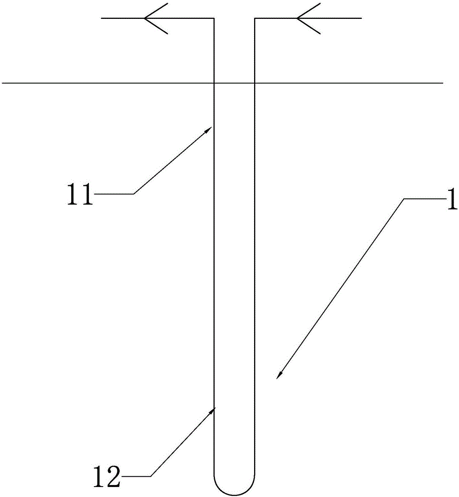
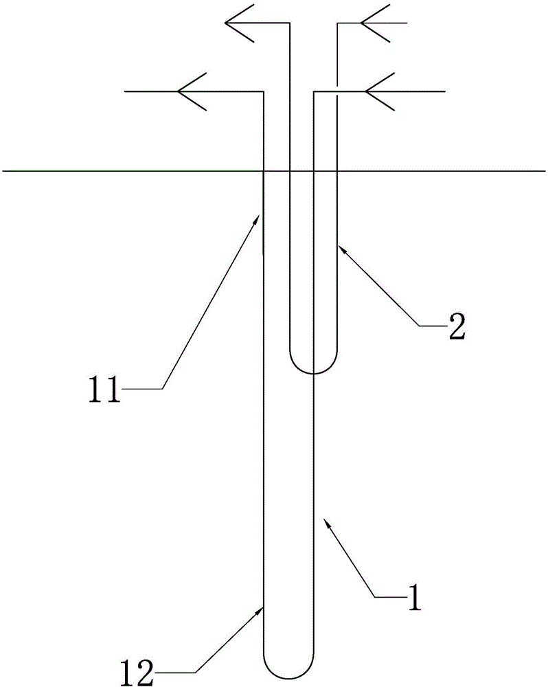
[0022] like figure 1 and figure 2 As shown, the medium-deep ground temperature compound mode heat exchange buried pipe device of the present invention includes a deep buried heat exchange pipe 1 buried in the underground soil, and the deep buried heat exchange pipe 1 is filled with a first heat exchange working medium and The two ends of the deep buried heat exchange tube 1 are connected to the user side, and at least one middle buried heat exchange tube buried in the underground soil and filled with the second heat exchange working medium is arranged on the upper end side of the deep buried heat exchange tube 1 2. Both ends of the middle buried heat exchange tube 2 are respectively connected to the user side, and the deep buried heat exchange tube 1 is divided into a heat preservation area 11 and a heat exchange area 12 from top to bottom, and all of the middle buried heat exchange tubes 2 or Locally located in the thermal insulation area 11, this embodiment uses the compou...

Embodiment 2

[0028]This embodiment is similar to Embodiment 1, except that the deep buried heat exchange tube 1 is located on the outer side of the tube wall of the heat preservation area 11 without an insulation layer, and the deep buried heat exchange tube 1 is located in the part of the heat preservation area 11 Exchange heat with the middle buried heat exchange tube 2; in this case, the deep buried heat exchange tube 1 diffuses the heat in the heat exchange area to the heat preservation area 11, so that the heat in the heat preservation area 11 is greatly increased, and one or more The heat exchange tube 2 buried in the middle layer collects the heat in the heat preservation area to enhance the heat exchange effect and heating effect of the buried heat exchange tube 2 in the middle layer. Multiple buried heat exchange tubes 2 in the middle layer can efficiently transfer heat to multiple different users One deep buried heat exchange tube 1 combines with the middle buried heat exchange tu...


PUM


Abstract

The invention provides a middle-deep ground temperature compound mode buried pipe heat exchange device, belongs to the technical field of heat exchange and heat conduction of geothermal energy, and solves the technical problems that in the prior art, a device is complex in structure, high in operation energy consumption, and low in heat exchange efficiency, and is likely to cause surface subsidence or threaten and pollute an underground water source. The heat exchange device comprises a deep buried heat exchange pipe filled with a first heat exchange working medium and buried in the undersoil. The two ends of the deep buried heat exchange pipe are connected with user sides. One or more middle buried heat exchange pipes filled with a second heat exchange working medium and buried in the undersoil are arranged on one side of the upper end of the middle buried heat exchange pipe. The two ends of the middle buried heat exchange pipe are separately connected with the user sides. The deep buried heat exchange pipe is divided into a heat insulation area and a heat exchange area from top to bottom. All or part of the middle buried heat exchange pipes are located in the heat insulation area. The heat exchange device has the advantages of being simple in structure, high in heat exchange efficiency and high in rate of geothermal utilization.

Description

technical field [0001] The invention belongs to the technical field of geothermal energy heat exchange and heat conduction, and in particular relates to a heat exchange buried pipe device. Background technique [0002] Geothermal energy is a kind of clean energy with huge reserves, and the rational development and utilization of geothermal energy is more and more favored by people. The deep geothermal technologies that have been developed and applied, such as geothermal power generation, geothermal heating, etc., mostly use the natural steam or hot water stored in the ground from geothermal wells to the surface for use, which is inefficient and will lead to ground subsidence over time; Irrigation technology will pose a threat and pollution to groundwater sources; the in-depth utilization of geothermal energy is affected by uncertain factors such as local geological conditions, the utilization range is small, and the technical conditions are harsh. These problems restrict the...

Claims


Application Information

Patent Timeline
Patent Type & Authority Applications(China)
IPC IPC(8): F24J3/08
CPCF24T10/15F24T10/20Y02E10/10
Inventor 赵正清黄以成代伯清
Owner ZHEJIANG LUTE ENERGY TECH
Why Eureka
Try Eureka