Discharge circuit

A discharge circuit and circuit technology, applied in the direction of measuring resistance/reactance/impedance, measuring electrical variables, measuring devices, etc., can solve the problems of increased back EMF, low power dissipation, danger, etc., and achieve simple structural design, reliable use, The effect of preventing and controlling the impact

Inactive Publication Date: 2017-05-10
GUANGXI UNIV FOR NATITIES
View PDF0 Cites 2 Cited by
  • Summary
  • Abstract
  • Description
  • Claims
  • Application Information

AI Technical Summary

Problems solved by technology

In order to reduce the reverse output voltage, the value of the discharge resistance is small, but its power dissipation is small under a certain current, so the discharge process is slow; at the same time, when the value of the resistance is large, the back electromotive force increases, which is dangerous. Low discharge time is too long, not suitable for work needs

Method used


Image

  • Discharge circuit

Examples


Embodiment Construction

[0019] The present invention will be further described below in conjunction with embodiment.

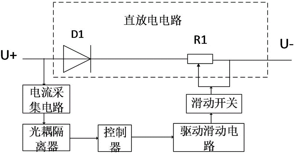
[0020] A discharge circuit such as figure 1 Shown, including direct discharge circuit, current acquisition circuit, optocoupler isolator, controller, drive slide circuit and slide switch. The present invention collects the current at the positive terminal of the transformer through the current collection circuit, and transmits the collected data to the controller, and the controller further controls the sliding switch to slide the sliding resistance R1 according to the size of the current to change the size of the resistance, so that the transformer can achieve rapid discharge Effect.

[0021] The input terminal of the direct discharge circuit is connected with the positive pole of the external transformer; the output terminal of the direct discharge circuit is connected with the negative pole of the transformer; the current collection circuit is connected with the positive pole of ...


PUM


Abstract

The invention provides a discharge circuit, and relates to the technical field of power detection. The discharge circuit comprises a direct discharge circuit, a current sampling circuit, an optical coupled isolator, a controller, a drive sliding circuit, and a sliding switch. The input end of the direct discharge circuit is connected with the positive electrode of an external transformer. The output end of the direct discharge circuit is connected with the negative electrode of the transformer. The current collection circuit is connected with the positive electrode of the external transformer. The output end of the current collection circuit is connected with the controller through the optical coupled isolator. The output end of the controller is connected with the sliding switch through the drive sliding circuit. The output end of the sliding switch is connected with the direct discharge circuit. The direct discharge circuit comprises a diode D1 and a sliding resistor R1. The positive electrode of the diode D1 is connected with the positive electrode of the external transformer. The negative electrode of the diode D1 is connected with the negative electrode of the external transformer through the sliding resistor R1. The sliding end of the sliding resistor R1 is connected with the sliding switch.

Description

technical field [0001] The invention relates to the technical field of power detection, in particular to a discharge circuit. Background technique [0002] Winding resistance of power transformers is an important parameter of transformers. This measurement is required for transformer semi-finished product test, factory test and on-site diagnosis. Therefore, it is necessary to design a circuit that can quickly discharge the energy of the transformer. [0003] Since the transformer winding is a very large inductance, in order to measure the accurate resistance value, a certain current must be applied. Therefore, the current applied to the winding during the measurement will generate a magnetic field in the transformer core, and the electrical energy will be converted into magnetic energy and stored in the core. When the measurement is finished, the test power supply is cut off to stop the power supply, and the magnetic field energy in the iron core will be released in the fo...

Claims


Application Information

Patent Timeline
Patent Type & Authority Applications(China)
IPC IPC(8): G01R1/36G01R27/02
CPCG01R1/36G01R27/02
Inventor 吴世贵
Owner GUANGXI UNIV FOR NATITIES
Why Eureka
Try Eureka