
360-degree full-field-angle diffraction optical element and design method therefor

A technology of diffractive optical element and design method, applied in the field of micro-optics, can solve the problems of limiting the range of diffracted light, limitation, etc.

Inactive Publication Date: 2017-05-10
NANJING HUAJIE IMI TECH CO LTD
View PDF0 Cites 9 Cited by
  • Summary
  • Abstract
  • Description
  • Claims
  • Application Information

AI Technical Summary

Problems solved by technology

But generally speaking, diffracted light can only be transmitted or reflected, that is, one of the two working modes, which limits the actual reachable range of diffracted light, and is widely used in light sensing, lidar, somatosensory, light display and other fields. will be very restricted

Method used


Image

  • 360-degree full-field-angle diffraction optical element and design method therefor
  • 360-degree full-field-angle diffraction optical element and design method therefor
  • 360-degree full-field-angle diffraction optical element and design method therefor

Examples


Embodiment Construction

[0029] The technical solutions of the present invention will be described in detail below in conjunction with the accompanying drawings.

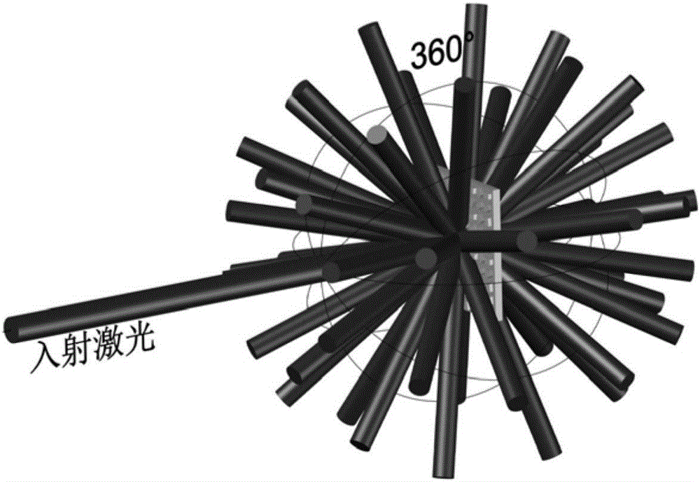
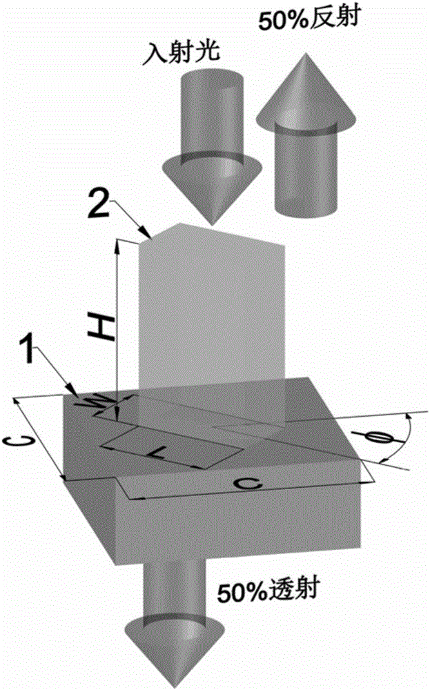
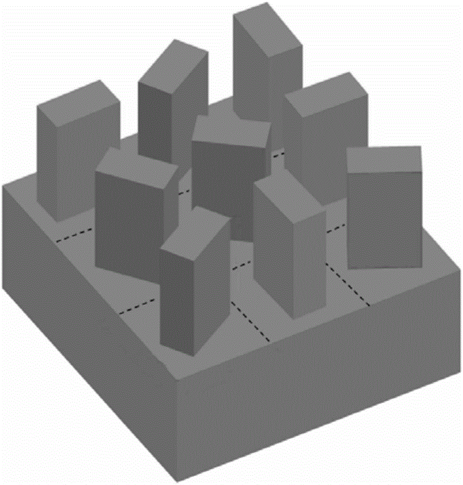
[0030] like Figure 1 to Figure 3 As shown, the present invention provides a diffractive optical element with a full field of view of 360°, including a base layer 1 made of a dielectric material and several nano-bricks 2, the base layer and the nano-bricks are transparent to the response wavelength, and the materials of the two are different; Among them, each nano-brick is a cuboid with the same size, and the length, width, and height of each nano-brick are all sub-wavelength scales; the nano-bricks are arranged on the base layer at different corners to form a unit structure. The phase of the incident light is modulated arbitrarily and continuously, and the modulated light field is transmitted forward and backward synchronously.

[0031] A 360° full field of view diffractive optical element of the present invention utilizes the magnetic re...


PUM


Abstract

The invention discloses a 360-degree full-field-angle diffraction optical element, and the optical element comprises a substrate layer made by a dielectric material, and a plurality of nano-bricks, wherein the dielectric material of the substrate layer and the dielectric material of the nano-bricks are different. The sizes of the nano-bricks are the same, and the length and width of the nano-bricks are at the scale of sub-wavelength. The nano-bricks are disposed on the substrate layer at different rotating angles, thereby forming a unit structure. The optical element can achieve the 360-degree diffraction angle, and achieves the forward and backward synchronous transmission of a modulated optical field. The invention also discloses a design method for the optical element.

Description

technical field [0001] The invention belongs to the field of micro-optics, and in particular relates to a 360° full field angle diffractive optical element and a design and realization method thereof. Background technique [0002] Diffractive Optical Elements (DOEs) are a class of optical elements that work on the principle of diffraction. Traditional diffractive optical elements control the phase of incident light by etching relief structures of different depths on transparent dielectric materials, and are ultimately used to make optical devices based on phase regulation. The diffraction angle that the incident light can expand after passing through the diffractive optical element is an important index to evaluate its performance. But generally speaking, diffracted light can only be transmitted or reflected, that is, one of the two working modes, which limits the actual reachable range of diffracted light, and is widely used in light sensing, lidar, somatosensory, light di...

Claims


Application Information

Patent Timeline
IPC IPC(8): G02B27/00G02B27/42
CPCG02B27/0012G02B27/42
Inventor 郑国兴周晓军李骊
Owner NANJING HUAJIE IMI TECH CO LTD
Learn More