Internal stress monitoring system for railroad bridge
A monitoring system and technology for internal stress, applied in force/torque/work measuring instruments, measuring devices, instruments, etc., can solve problems such as failure to meet actual use needs, few stress monitoring devices for railway bridges, etc. The effect of large expansion and deformation ability
- Summary
- Abstract
- Description
- Claims
- Application Information
AI Technical Summary
Problems solved by technology
Method used
Image
Examples
Embodiment 1
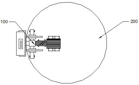
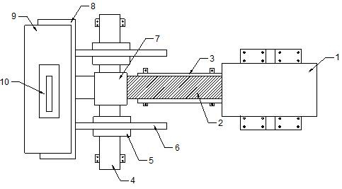
[0039] combine figure 1 and figure 2 , an internal stress monitoring system for railway bridges, comprising a fixed plate 200 and a force-applying mechanism 100 arranged on the fixed plate 200, one force-applying mechanism 100 is provided, and the one force-applying mechanism 100 is arranged along the fixed plate 200 radial setting.
[0040] The force applying mechanism 100 includes a cylinder 1, a screw rod 2, a support rod 4 and a stress sensor 9, the support rod 4 and the cylinder 1 are all bolted on the fixed plate 200, and the outside of the screw rod 2 is provided with a guide cylinder 3 , the guide cylinder 3 is fixedly connected to the fixed plate 200 by bolts, one end of the screw 2 is connected to the output end of the cylinder 1, and the other end of the cylinder 1 is connected to the stress sensor 9 through the lead block 7, and the stress sensor A mounting frame 8 is provided outside the side of the device 9 facing the support rod 4, the guide block 7 and the g...
Embodiment 2
[0043] combine figure 2 , two force-applying mechanisms 100 are provided, and the two force-applying mechanisms 100 are arranged along the radial direction of the fixed plate 200, and the stress sensors 9 of the two force-applying mechanisms 100 are intersected at 90°, and can be monitored simultaneously Horizontal stress and vertical stress, a certain stress sensing probe 10 of two stress sensors 9 is aimed at the vertical direction, and another stress sensing probe 10 is then aimed at the horizontal direction, and the stress sensor is slowed down with the screw rod 2 and the lead block 7 9 is slowly sent to the designated position, and the two stress-sensing probes 10 are pressurized and monitored respectively.
Embodiment 3
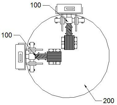
[0045] combine image 3 , there are three force applying mechanisms 100, and two of the three force applying mechanisms 100 are distributed along the radial direction of the fixed disk 200, and the stress sensors 9 of the two force applying mechanisms 100 are at 90° Intersecting arrangement, the other of the three force-applying mechanisms 100 is arranged along the central axis of the fixed disk 200, and any stress induction probe 10 of the two radial stress induction probes 10 of the stress inductor 9 in three directions is paired quasi-vertical direction, the other radial stress sensing probe 10 is aimed at the horizontal direction, and the three-way stress sensing probe 9 is slowly sent into the bottom of the hole with the screw 2. When pressurizing, pressurize the two stress sensing probes 10 respectively , and finally inject pressure on the radial stress sensing probe 10, and monitor after the injection pressure is completed.
[0046] During the measurement process, the ...
PUM
 Abstract
Description
Claims
Application Information
 - R&D
- Intellectual Property
- Life Sciences
- Materials
- Tech Scout
- Unparalleled Data Quality
- Higher Quality Content
- 60% Fewer Hallucinations
Browse by: Latest US Patents, China's latest patents, Technical Efficacy Thesaurus, Application Domain, Technology Topic, Popular Technical Reports.
© 2025 PatSnap. All rights reserved.Legal|Privacy policy|Modern Slavery Act Transparency Statement|Sitemap|About US| Contact US: help@patsnap.com


