
Fiber bragg grating high-temperature stress testing device and mounting method of device

A test device, high-temperature strain technology, applied in the direction of measuring devices, optical devices, instruments, etc., can solve problems such as strain, and achieve the effects of high strain measurement accuracy, easy mass production, and good temperature compensation

Inactive Publication Date: 2015-05-06
BEIJING INST OF STRUCTURE & ENVIRONMENT ENG +1
View PDF6 Cites 16 Cited by
  • Summary
  • Abstract
  • Description
  • Claims
  • Application Information

AI Technical Summary

Problems solved by technology

[0005] The purpose of the present invention is to provide a fiber grating high-temperature strain test device and its installation method in a high-temperature radiation heating environment, so as to solve the problem of strain measurement in a high-temperature environment

Method used


Image

  • Fiber bragg grating high-temperature stress testing device and mounting method of device
  • Fiber bragg grating high-temperature stress testing device and mounting method of device
  • Fiber bragg grating high-temperature stress testing device and mounting method of device

Examples

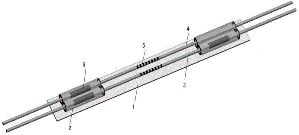
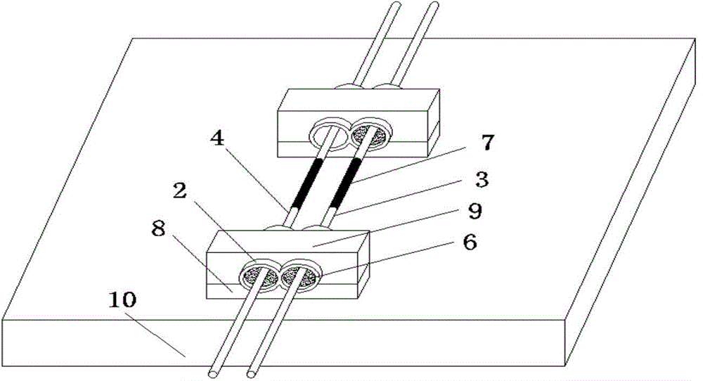
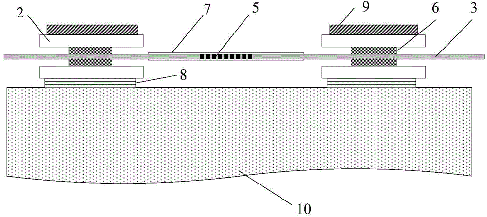

Embodiment Construction

[0026] The present invention will be further described below in conjunction with the accompanying drawings and embodiments.

[0027] The present invention is a high temperature strain test device based on fiber Bragg grating (FBG), the structure of the test device is as follows: figure 1 As shown, it includes a temporary base 1, two "8" shaped quartz tubes 2 fixed on the temporary base 1, a strain sensing optical fiber 3 and a temperature reference optical fiber 4 passing through the two "8" shaped quartz tubes; Fabricate Bragg grating 5, strain sensing fiber 3 and temperature reference fiber 4 collectively referred to as grating fiber 3,4. Wherein, the temporary substrate 1 adopts a material with a low expansion rate to prevent the high expansion rate from stretching the grating optical fibers 3 and 4 when the ambient temperature changes; the "8"-shaped quartz tube 2 is to weld two quartz tubes together, There are two groups of thin tubes formed with double-hole channels, th...


PUM


Abstract

The invention relates a fiber bragg grating high-temperature stress testing device applied to a structural heat test radiation heat environment and a mounting method of the fiber bragg grating high-temperature stress testing device. The device comprises a stress sensing optical fiber (3) which is equipped with a fiber bragg grating (5), two 8-shaped quartz tubes (2) and a temperature reference optical fiber (4), wherein the temperature reference optical fiber (4) is the same as the stress sensing optical fiber (3); the stress sensing optical fiber (3) and the temperature reference optical fiber (4) respectively pass through the two 8-shaped quartz tubes (2) to be parallel; the stress sensing optical fiber (3) is integrally fixed to the two 8-shaped quartz tubes (2) through fixing materials (6); the temperature reference optical fiber (4) is only integrally fixed to one 8-shaped quartz tube (2), and the other end of the temperature reference optical fiber (4) is suspended. With the adoption of the device, the temperature of degeneration of the fiber bragg grating at high temperature is solved; the device is applicable to the heat test environment at the temperature close to 1000 DEG C and achieves the high-temperature stress measurement of a composite material structural part.

Description

technical field [0001] The invention relates to an optical fiber Bragg grating high-temperature strain test device and an installation method thereof, which are applied in the radiation heat environment of a structural heat test, and belong to the technical field of high-temperature strain measurement. Background technique [0002] Structural thermal strength test technology is a ground simulation test technology developed to solve the aerodynamic heat problem of aircraft flying at supersonic speed. With the rapid increase of the flight speed of the aircraft, the aerodynamic and thermal environment experienced by the aircraft has become increasingly severe, and the temperature of the windward side, rudder and other structures can reach thousands of degrees. At such a high temperature, the high temperature strain test device of the structure has become the main factor restricting the thermal strength test of the structure. [0003] Existing high-temperature strain measuremen...

Claims


Application Information

Patent Timeline
Patent Type & Authority Applications(China)
IPC IPC(8): G01B11/16
Inventor 孔凡金张伟刘宝瑞王智勇靳荣华
Owner BEIJING INST OF STRUCTURE & ENVIRONMENT ENG
Learn More