Display panel and display device

A technology for display panels and array substrates, applied in static indicators, nonlinear optics, instruments, etc., can solve the problems of occupying the frame width of the display device, and it is difficult to realize the narrow frame design of the display device, and achieve the effect of realizing the narrow frame design.

Inactive Publication Date: 2017-05-10
BOE TECH GRP CO LTD +1
View PDF2 Cites 43 Cited by
  • Summary
  • Abstract
  • Description
  • Claims
  • Application Information

AI Technical Summary

Problems solved by technology

[0004] The disadvantage of the existing technology is that the binding part of the array substrate is generally arranged in the non-display area of...

Method used


Image

  • Display panel and display device
  • Display panel and display device
  • Display panel and display device

Examples


Embodiment Construction

[0024] In order to realize the narrow frame design of the display device, the embodiments of the present invention provide a display panel and a display device. In order to make the purpose, technical solution and advantages of the present invention clearer, the following examples are given to further describe the present invention in detail.

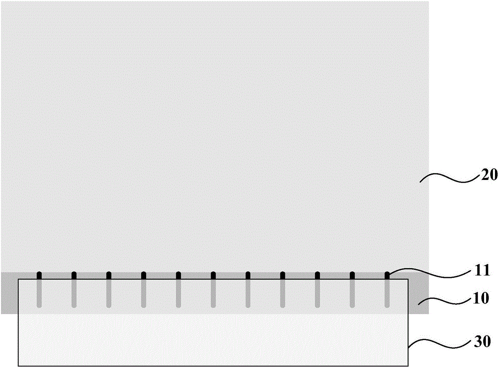
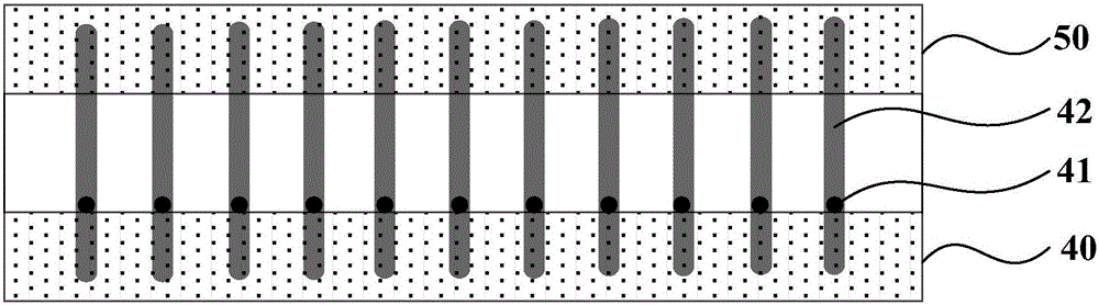
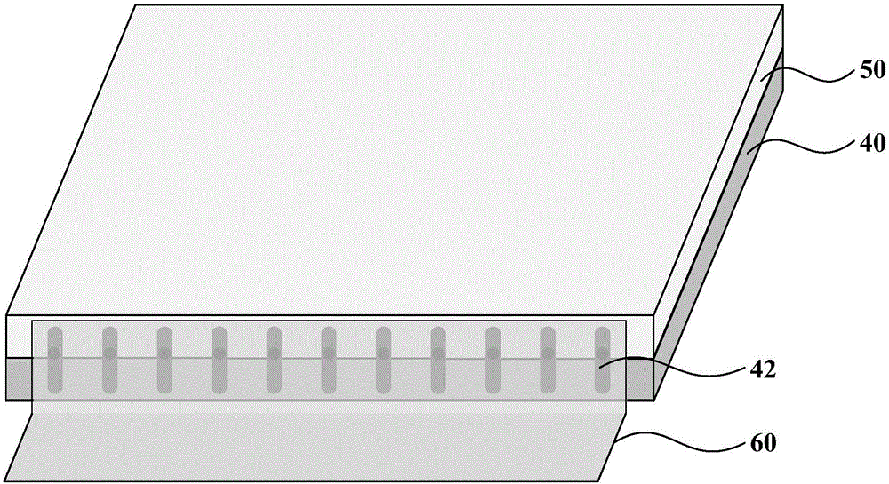
[0025] Such as figure 2 and image 3 As shown, the display panel provided by the embodiment of the present invention includes a display panel body and at least one flexible circuit board 60, and the display panel body includes an array substrate 40 and a color filter substrate 50 arranged oppositely, wherein:

[0026] Several metal leads 41 are arranged on the array substrate 40; a binding part is arranged at the end of the display panel body, and the binding part includes a metal connection wire 42 arranged corresponding to each metal lead 41 and electrically connected to the metal lead 41; at least one The flexible circuit board 60...


PUM


Abstract

The invention discloses a display panel and a display device. The display panel comprises a display panel body and at least one flexible circuit board. The display panel body comprises an array substrate and a colored film substrate arranged in opposite positions, wherein the array substrate is provided with several metal guide wires. The end portion of the display panel is provided with a binding part. The binding part comprises metal connecting wires which are arranged respectively for each metal guide wire and are electrically connected with the metal guide wires. At least one flexible circuit board is connected electrically with the binding part. Compared with the prior art, the display panel is beneficial to achieve the narrow frame design of the display device.

Description

technical field [0001] The present invention relates to the field of display technology, in particular to a display panel and a display device. Background technique [0002] Among flat panel display devices, Thin Film Transistor Liquid Crystal Display (TFT-LCD) has the characteristics of small size, low power consumption, relatively low manufacturing cost and no radiation, and occupies a dominant position in the current flat panel display market. . [0003] Such as figure 1 As shown, the display panel of TFT-LCD generally includes a display panel body and a flexible circuit board 30, wherein: the display panel body includes an array substrate 10 and a color filter substrate 20 oppositely arranged, the array substrate 10 includes a part beyond the color filter substrate, and the array The substrate 10 is provided with a binding part 11 on the side facing the color filter substrate 20 at the part beyond the color filter substrate, and the flexible circuit board 30 is bound t...

Claims


Application Information

Patent Timeline
IPC IPC(8): G02F1/1345G02F1/1333G02F1/133
CPCG02F1/13452G02F1/133G02F1/1333
Inventor 贾鹏王宝强胡巍浩贾丽丽田春光夏天宇
Owner BOE TECH GRP CO LTD
Why Eureka
Try Eureka