Display panel

A display panel and display area technology, applied in photovoltaic power generation, optics, instruments, etc., can solve the problems that cannot meet the mass production conditions of non-traditional rectangular display devices

Active Publication Date: 2017-05-10
INNOLUX CORP
View PDF9 Cites 2 Cited by
  • Summary
  • Abstract
  • Description
  • Claims
  • Application Information

AI Technical Summary

Problems solved by technology

However, conventional manufacturing processes cannot meet the conditions for mass production of display devices with non-traditional rectangular shapes.

Method used


Image

  • Display panel
  • Display panel
  • Display panel

Examples


Embodiment Construction

[0102] The following description details the display panel of the present invention. In order to make the objects, features, and advantages of the present invention more comprehensible, the following specific embodiments are described in detail together with the accompanying drawings. Wherein, the configuration of each element in the embodiment is for illustration, not for limiting the present invention. Moreover, part of the reference numerals in the embodiments is repeated, for the sake of simplicity of description, it does not imply the correlation between different embodiments. In addition, in order to clarify the size, positional relationship, etc. of members shown in the drawings, they may be exaggerated.

[0103] The directional terms mentioned in the following embodiments, such as: up, down, left, right, front or back, etc., are only directions referring to the attached drawings. Accordingly, the directional terms are used to illustrate and not to limit the invention...


PUM


Abstract

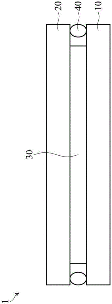
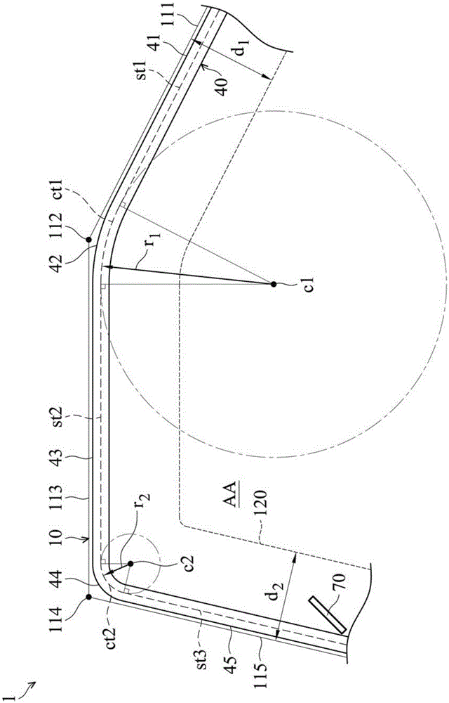
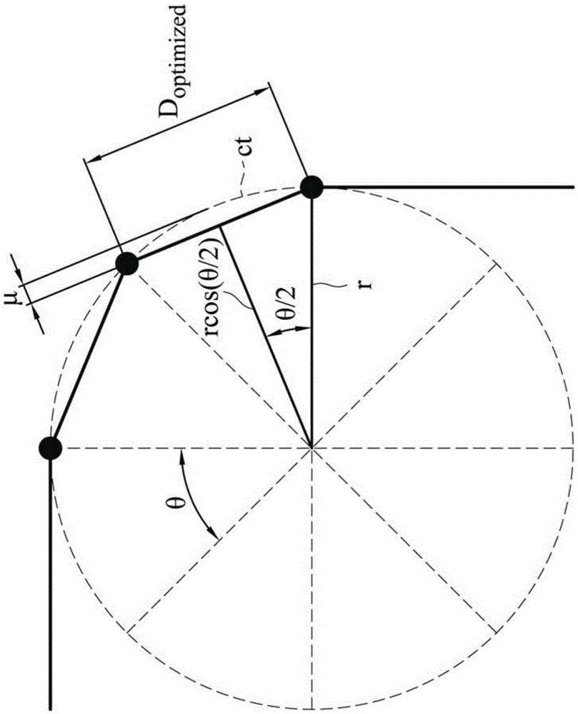
A display panel is provided, which includes a sealant connected between two opposite substrates. A first curved segment of the sealant includes first nodes. The first nodes each include a first node center distributed over a first curved coating trajectory. A second curved segment of the sealant includes second nodes. The second nodes each include a second node center distributed over a second curved coating trajectory. The radius of rotation of the first curved coating trajectory is greater than the radius of rotation of the second curved coating trajectory. In addition, the distance between the first node centers is greater than the distance between the second node centers.

Description

technical field [0001] The present invention relates to an electronic component, and in particular to a non-rectangular electronic display panel and a method for manufacturing the same. Background technique [0002] An electronic display device is an optoelectronic device that converts electronic signals into visible images, allowing viewers to view the information carried in the electronic signals. In recent years, electronic display devices such as liquid crystal displays and organic electroluminescence displays have become the mainstream of display products. [0003] The above-mentioned electronic display devices have been widely used in various portable electronic products such as notebook computers, tablet computers, personal assistants, and portable In mobile phones, and replace the traditional TV and cathode ray tube display screen. [0004] In order to meet the ever-changing demands of modern electronic products, the industry needs to further consider its appearanc...

Claims


Application Information

Patent Timeline
IPC IPC(8): G09F9/00G02F1/1339
CPCG02F1/1339G09F9/00H10K59/8722Y02E10/549G02F2201/56Y02P70/50H10K77/10H10K50/8426
Inventor 颜崇纹王兆祥吴仕雄彭焕光赖瑞菊
Owner INNOLUX CORP
Why Eureka
Try Eureka